


A NEW GUY OILE
Page 46
Page 47
Page 48
If you've noticed an error in this article please click here to report it so we can fix it.
FOR BUS WORK
THE year 123 will be remembered, so far as transport work is concerned, by the number of chassis which has been designed and produced specially to cater for the requirements Of the oil engine. This may appear to be something of an anachronism, but it will be recalled that, when oil engines were first used for road service, most manufacturers adapted the petrol-engined-chassis designs already in existence. Now, due to the fact that the compression-ignition engine has firmly established itself, special chassis are being produced which have been designed to suit the different performance characteristics (from the petrol unit) of the more economical engine.
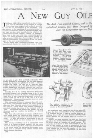
Falling under such a heading is the new Guy Arab Tour-wheeled chassis for double-deck buses, of which we are able to give first and full particulars. This chassis is modern in all respects, and has been designed to suit the Gardner six-cylindered oil unit. All components are robust, yet they are of relatively light weight, as is evidenced by the fact that the complete chassis scales but 4 tons 1 cwt. ready for the road ; important changes from previous Guy practice are notice. able.
Actually, few of the leading dimensions have been materially altered, the wheelbase being 16 ft. 7+ ins., the front-wheel track 6 ft. 5+ ins., and the rear-wheel track 5 ft. 10 ins., whilst the length and width of the chassis work out at 25 ft. 7 ins. and 7 ft. 6 ins. respectively. When examining details, however, many differences become apparent.
The substantial frame, for example, has side members 11 ins, deep midway between the axles, whilst in plan view they (the side members) are splayed out at the rear to a point where only working clearance is provided between the sides of the channels and the tyres. The springs lie immediately beneath the side members and are retained in position by divided shackles.
This form of construction, of course, tends to minimize rolling when the vehicle is being cornered fast (the overturning couple varies inversely as the springbase). To keep all points of attachment as low as possible, both front and rear springs have a reverse camber.
The bracing amidships is of a substantial order. There is a channel-sectioned member, 10+ ins, deep, fore and aft% of the-gearbox, and large-diameter tubes at the points where the rear-spring anchorages occur, whilst there is a further heavy tubular member inunediately behind the clutch.
J332
An interesting point concerning the frame assembly is that the front cross-member—a 3-in, diameter tube —is arranged so that it can be readily detached by undoing three bolts per side, thereby greatly facilitating removal of the engine when an overhaul is necessary.
Contrary to usual practice, the axle pot has been placed on the off side of the chassis—a point of design for which there is a number of sound reasons. The main idea is to throw a little more weight to the off side of the vehicle, in order -to counteract, in some measure, the natural tendency of the bus to heel over when running on the near-side camber of the road. Furthermore, there is less obstruction on the body platform when the now-fashionable straight staircase is used.
This argument is even more forcible in bus designs incorporating an off-side gangway in the upper saloon, which tends to cause more and more weight to be thrown on to the near side of the chassis.
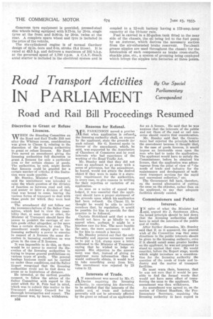
The forward position for the driver has been adopted, and, due to the inclination of the engine to the off side, the driver's seat has had to be placed rather farther sideways than usual. Both the engine and gearbox are mounted on Floatex bushes, the engine being slung in the frame at four points, whilst the separately mounted gearbox is retained by three connections. The method of mounting this component is rather interesting, for a channel member runs for the length of the box on the near side and is retained at eaCh end by brackets attached to the frame cross-members On the off side, a single attachment by a Floatex bush is made to the main channels, thus the box is relieved of all stress due to road shocks or distortion. The ratios standardized for the indirect forward gears are 1.58, 227 and 423 to 1, reverse being 4.06 to 1.
A large single-plate clutch having 298.4 sq. ins, of working area is operated in the ordinary way by multiplying levers, the ends of these being hardened and operated in hardened-steel bushes. The free-member has a ball-bearing spigot, whilst the withdrawal mechanism is carried on outrigger brackets from a cross-member, the operating shaft being equipped with spherical oilless bearings.
A short clutch shaft equipped with Simms Jurid armoured flexible joints transmits the drive to the gearbox, the final• drive being by a Hardy Spicer tubular propeller shaft with a universal joint at the front and rear. The ratio of the worm wheel to the worm in the rear axle is 4.8 to 1, giving a maximum road speed of 38 m.p.h, at the governed engine sPeed of 1,700 r.p.m.
The layout of the brakes is particularly interesting, because a special four-shoe rear assembly is utilized in conjunction with a two-shoe set of front brakes, the total friction area being 620 sq. ins—a notable figure for a four-wheeled vehicle. A push-on brake lever is situated on the right-hand side of the driver and is coupled to the pedal-operated system, the main crossshaft having a three-point attachment, so that the system conforms with the latest Ministry of Transport requirements.
Thus, the pedal and the lever apply 'ail brakes, the former set being equipped with a Dewandre vacuum servo which is coupled to a reservoir having a capacity of 2,180 cubic ins.; an exhauster mounted on the engine maintains the correct negative pressure. The frontwheel drums are 17 ins, in diameter and, with shoes 3 ins, wide, provide a total friction area of 168 sq. ins. Drums of 161-in. diameter at the rear carry four shoes 4i ins. wide, giving a friction area of 452 sq. Ins.
As has already been indicated, the four shoes in each rear drum operate simultaneously—an arrangement which equalizes pressure and does not cause drum distortion. It may be mentioned that the servo motor is placed relatively high up beneath the driver's seat, where it is readily accessible. Generous tyre equipment is provided, pressed-steel disc wheels being equipped with 9.75-in. by 20-in, single tyres at the front and 9.00-in. by 20-in, twins at the rear. A complete spare wheel and tyre is included in the price of the vehicle.
The six-cylindered engine is of normal Gardner design of 41-in. bore and 6-in. stroke (8.4 litres). It is rated at 43.5 h.p. and delivers a maximum of 102 b.h.p. at the governed speed of 1,700 r.p.m. A C.A.V.-Bosch axial starter is included in the electrical system and is coupled to a 12-volt battery having a 173-amp.-hour capacity at the 10-hour rate.
Fuel is carried in a 35-gallon tank fitted to the near side of the chassis, the oil being led to the fuel pump by an Autovac, which derives the necessary suction from the air-exhausted brake reservoir. Tecalemit grease nipples are used throughout the chassis for the lubrication of such components as brake cross-shafts, shackle pins, etc., a system of grouping being employed which brings the nipples into batteries at three points.