


A VERY PROMISING SELF-ASSISTED BRAKE.
Page 30
If you've noticed an error in this article please click here to report it so we can fix it.
A Resume of Recently Published Patent Specifications.
MHE brake shown in specification Na. 233,933, by the Studebaker Corporation of America, appears to be a very simple and practical arrangement in which the movement of the vehicle is employed to assist in causing pressure between the shoe and the drum.
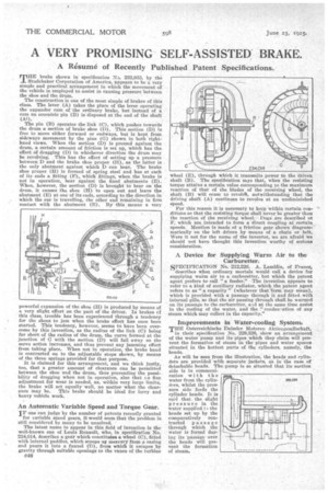
The construction is one of the most simple of brakes of this class. The lever (A) takes the place of the lever operating the expander cam of the ordinary brake, but instead of a cam an eccentric pin (B) is' disposed at the end of the shaft (Al). .• The pin (B) operates the link (C), which pushes towards the drum a section of brake shoe (D). This section (D) la free to move either forward or endways, but is kept from sideways movement by the pins (G) shown in both 'righthand views. When the section (D) is pressed against the drum, a certain amount of friction is set up, which has the effect of dragging (D) in whichever direction the drum may be revolving. This has the effect of setting up a pressure between D and the brake shoe proper (H), as the latter is the only abutment against which D can bear. The brake shoe proper (1) is formed of spring steel and has at each of its ends a fitting (F), which fittings, when the brake is not in operation, bear against the fixed abutments (E). When, however, the section (D) is brought to bear on the drum, it causes the shoe (H) to open out and leave the abutment (E) at one of its ends, according to the direction in which the car is travelling, the other end remaining in firm contact with the abutment (E). By this means a very powerful expansion of the shoe (H) is produced by means of a very slight effort on the part of the driver. In brakes cf this class, trouble has been experienced through a tendency for the shoes to jam when the brake effect has once been started. This tendency, however, seems to have been overcome by this invention, as the radius of the link (C) being far short of the radius of the drum, the curve formed at the junction of C with the section (D) will fall away as the servo action increases, and thus prevent any jamming effect from taking place. When not in operation, the brake band is contracted on to the adjustable stops shown, by means of the three springs provided for that purpose.
It is claimed for this arrangement, and we think justly, too, that a greater amount of clearance can be permitted between the shoe and the drum, thus preventing the possibility of dragging when not in operation, also that 7-0 fine adjustment for wear is needed, as, within very large limits, the brake will act equally well, no matter what the clear
ance may be. This brake should be ideal for lorry and heavy vehicle work.
An Automatic Variable Speed and Torque Gear.
IF one can judge by the number of patents recently granted for variable speed gears, it would seem that the problem is still considered by many to be unsolved.
The latest name to appear in this field of invention is the well-known one of Louis Renault, who, in specification No. 234,014, describes a gear which constitutes a wheel (C), fitted with internal paddles, which scoops up mercury from a casing and pours it into a funnel (D), from which it escapes by gravity through suitable openings to the vanes of the turbine CM wheel (E), through which it transmits power to the driven shaft (B). The specification says that, when the resisting torque attains a certain value corresponding to the maximum reaction of that of the blades of the receiving wheel, the shaft (B) will cease to revolA, notwithstanding that the driving shaft (A) continues to revolve at an undiminished speed.
For this reason it is necessary to keep within certain conditions so that the resisting torque shall never be greater than the reaction of the receiving wheel. Dogsare described at F, which are intended to form a direct coupling at certain speeds. Mention is Made of a friction gear shown diagrammatically on the left driven by means of a chain or belt. Were it not for the name of the inventor, we are afraid we should not have thought this invention worthy of serious consideration.
A Device for Supplying Warm Air to the Carburetter.
SPECIFICATION No. 212,229. A. Lamblin, of France, describes what ordinary mortals would call a device for supplying warm air to a carburetter, but which the patent agent prefers to call "a feeder." The invention appears to refer to a kind of auxiliary radiator, which the patent agent refers to as "a capacity" (whatever that term may mean), which is provided with a passage through it and fitted with internal gills, so that the air passing through shall be warmed on its passage to the carburetter, and at the same time assist in the cooling of the water, and the ." condee-ation of any steam which may collect in the capacity."
Improvements in Water-cooling System:
THE Osterreichische Daimler Motoreu .kktiengesellschaft, in their, specification No. 229,328, show an arrangement of the water pump and its pipes which they claim will prevent the formation of steam in the• pipes and water spaces situated in the hottest parts of the cylinders, namely, the heads.
As will be seen from the illustration, the heads and cylinders are provided with separate jackets, as in the case of detachable heads. The_ pump is so situated that its suction side is in communication with the water from the cylinders, whilst the pressure side feeds the cylinder heads. It is said that, the slight pressure in the water supplied t ) the heads set up by the comparatively contracted passage through which the water is forced during its passage over the heads will prevent the formation of steam.