


ROAD WAGON EXPERI N RAIL CAR DESIGN.
Page 16
Page 17
Page 18
If you've noticed an error in this article please click here to report it so we can fix it.
How the Rail Car Engineer is Taking _A Experience Gained in the Desigi
the Constructional and Maintenance ation of Steam Road Wagons.
riOMMERCIAL motor influences towards ex treme refinement in the design and construction of power units and transmissions have been very powerful, whilst the extraordinary develop ment of mechanical road transport has called for quantity production attainable only when the strictest accuracy has made interchangeability practicable. This in its turn has created a demand for higher and higher grades of machine tools, so that it is justifiable to-day to claim that engin eering production has, in consequence of. the developments in traffic and transport during the past two decades, made a very substantial advance, the design and manufacture of railway rolling stock being one of a number of industries which has benefited.
One of the reasons why the greatest possible efficiency has been vital to the road motor Is the fact that, whereas the track resistance of a rail way wagon is about 10 to 12 lb. per ton, the road resistance of a motor lorry on a good hard road is about 60 lb. per ton. This has constituted a some what severe handicap that has, however, been very largely overcome by skin in design and manufac ture aiming at securing the greatest possible amount of power and efficiency from the smallest possible amount of raw material.
There is thus a great deal in common between the road motor, whether driven by a steam engine or an internal-combustion engine, and the most modern types of self-contained railway coach. Each acts as a unit and not as Dart of a train, and the moat satisfactory mode of operating each is on a short or medium haul, although in case of need a long haul is perfectly feasible. Again, the self-contained type of railway coach and the road motor are very largely produced in the same works, and it is not unusual for some of the com ponents of each to be interchangeable, thus, of course, effecting an economy in manufacturing costs.
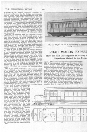
One of the latest productions of a concern which has specialized on the construction of road motors of all types, from the smallest up to the most powerful caterpillar tractors made for use in the Great War, is the Clayton railway steam car constructed by Clayton Wagons, Ltd. (associated with Clayton and Shuttleworth, Ltd.), of Lincoln. Their experience extends over many years. and, in consequence, they have been able to incorporate in the design only such features as are of proved reliability for railway service, and to adont the best practices in railway-carriage manu facture and in steam engineering. The ran coach has been designed as a means of handling passenger traffic on main lines during the non-rush periods of the day, when the greater handi ness, the rapid acceleration and economical deceleration of the single coach offer material advan tages, and also as an instrument for the development and exploitation of branch-line services. The ear which we are about to de scribe has been built to the order and specification of the New Zealand Government Railways, under the inspection of Messrs. Preece, Cardew. and Rider.
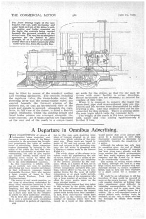
From our drawings it will be seen that the body of the coach, is carried at each end on a swimring bolster, each bolster being disposed midway between the axles of its respective bogie, and a double-coil spring being fitted under the end of each bolster. The inclined swing links are short and the side bearers are spaced widely e32 apart. The headstocks are arranged for the reception of the standard buffing and drawgear of the New Zealand Government Railway, whilst the centre pivot at the engine end of the coach is designed to take buffing and drawgear stresses. The wheelbase of the driving bogie is 7 ft. and that of the trailer bogie 5 ft. 6 inS., the distance between bogie centres being 42 ft. The overall length of the coach (which is for 3-ft. 6-in.-gauge permanent-way) is 55 ft., whilst the width is 8 ft. 2R. ins, and the height 11 ft. 5i ins. Curves of three chains radius can be negotiated with ease and safety. As the boiler and engine are mounted on the driving bogie, it is obvious that the boiler, being at the rear of the bogie, must swing to one side or the other of the driver's cab whenever a straight line is departed from; but, even on a minimum curve of the radius given, the total movement of the boiler from the centre-line is only 3i ins., so that the arrangement, whilst offering many advantages in construction and in power-unit detachability, entails no disadvantage. To permit of the necessary, funnel movement, the roof of the cab has an elongated hole, the funnel having a large cowl which completely covers the hole. When it is required, to remove or replace the driving bogie the chimney stack is removed, the end of the coach is lifted and the bogie is then pulled We need not do more than refer briefly to the coach. It is mounted on an underframe of rolledsteel channels provided with fixed angle trusses, the body and roof framing being of rolled-steel sections, whilst the body and roof panels are char coal-finished plates. Two cross-partitions separate the front and rear driving compartments (for, as is explained later, the coach can be driven from each end) from the passenger compartment, which is entered by doors at the forward end. Comfortably padded seats are provided for 57 passengers, and the coach is equipped with luggage racks, side ventilators, curtains to the windows, torpedo root ventilators with regulators and clectric lighting.
The power unit consists substantially of the standard engine and boiler as fitted in the welltried Clayton undertype steam road wagon, but modified in detail for application to the railway steam car. The engine is mounted on bearings on the forward axle of the driving bogie and is suspended by a link from one of the bogie crossbearers. A hardened steel pinion on the engine crankshaft drives a hardened-steel spurwheel on the axle. The gears are generously proportioned, are totally enclosed and run in oil. The reliability of this method of driving is attested by its universal use in electric traction.
Each cylinder is 61 ins, in diameter and the piston stroke is 10 ins. The crankcase is a steel casting and the housings for the engine bearings on the axle are cast integral with the crankcase. These engine bearings are of bronze, lined with white metal and are pad-lubricated from a well in each housing. The engine crankshaft is mounted on roller bearings and is balanced. The engine is of the two-cylinder high-pressure type, with all parts totally enclosed. Distance pieces are provided to allow access to the cylinder glands and to prevent leakage of moisture into the crankcase. Piston valves are used to control the steam to each cylinder, and reversing is effected by means of a single eccentric enclosed in the crankcase and perfectly lubricated, giving a large range of cut-off.
The boiler is of the vertical water-tube type constructed to withstand a working pressure of 230 lb. per sq. in, and tested to 400 lb. per sq. in. The tubes are straight and are inclined upwards across the firebox, and the whole of the latter can be unbolted and dropped out for examination at any time. An exhaust steam water-heater of efficient design is provided and a coil superheater is arranged in the top of the boiler, giving a superheat of approximately 100 degrees F. The heating surface of the boiler is 51 sq. ft., and the fire-grate area 3.27 sq. ft.
The boiler evaporates about 1,200 lb. of water Per hour, and with coal of a calorific value of 14,000 E.T.U. the fuel consumption is 4.8 lb. per mile. Under average conditions about 4 gallons of watei are needed per train-mile. The ear has a water tank of 550 gallons capacity and a coal hopper of 15 cwt. capacity. These are contained in the forward part of the bogie above the front axle.
At an engine speed of 350 r.p.m. a coach speed of 35 m.p.h. is attained, with an extra, 5 miles per hour for each 50 revolutions of the engine.
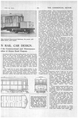
The axles of the driving bogie are coupled through side rods. A cast-steel spoked type of wheel centre is used, balanced to compensate for the side rods and pressed on to forged steel axles. In order to facilitate replacements from stock, the standard pattern tire of the New Zealand Government Railways has been fitted to each wheel.
From the coal bunker a chute extends into the driver's cab, and both coal hunker and water tank c33,. may be filled by means of the standard coaling and watering appliances. The controls, including the regulator valve, the zteam-brake valve, the reversing lever and the steam-whistle valve, are carried beneath the forward window of the driver's cab, so that an Unrestricted view of the track and signals is secured. Alongside the regulator, In full view of the driver, is fitted a Detroit engine lubricator, whilst the sanding pedals and hand brake column are arranged alongside the other controls. All of these controls are duplicated at the rear end of the• coach in a compartment set aside for the driver, so that the car may be driven with equal facility in either direction. Hence turntables are not necessary at termini for coaches of this type. When it is required to remove the bogie the steam-feed pipe and steam-exhaust pipe are disjointed and the reverse lever disconnected by withdrawing a pin. The rear controls need not be disconnected for this purpose. There is nothing about the rear bogie which calls for comment here. The weight of the coach is 20i tons, provisioning with water and coal adding approximately a further 3 tons.