


Improvements in Injection Pump Governors
Page 54
If you've noticed an error in this article please click here to report it so we can fix it.
A Résumé of Recently Published Patent Specifications
A CCORDING to patent No. 598,718, .1-1 in the usual injection-pump governor, the spring acts on the centrifugal weights through sliding sleeves, which results in the sleeves being subjected to considerable wear. To avoid this is the object of an improved spring shown in patent No. 598,718, by S. A. Adolphe Saurer, Arbon, Switzerland.
• The spring, in this case, works axially along the spindle and revolves with it. In the drawing, 1 is the spring, 2 the centrifugal bob-weights, and 3 a sliding sleeve connected to the weights by a rack-and-quadrant mechanism (4). This element controls the rack-bar (5) of the output control.
A second sleeve (6) is set by the speed-control rod (7) and this, by shifting the fulcrums of a pair of bellcranks (not shown in the drawing), alters the effective spring force. The geometry of the system is such that the governor sleeve is loaded in accordance with a square-law, so that a constant governing ratio is obtained over the whole speed range.
INCREASING THERMAL EFFICIENCY E fact that, in the average internal
combustion engine, 70 per cent, of the heat in the fuel goes to waste, has set many inventors to work to ascertain if more could be usefully employed, and a possible method is outlined in patent No. 599,446, by B. Robson. "The Frith," Hillcrest Avenue, Huyton Quarry, Liverpool.
This inventor suggests that if a small quantity of water were to be injected into the combustion chamber during the power stroke, it would assist the effort by pressure created by the generation of steam. To inject the water, it is proposed that a pump, similar to one of the fuel-injection type, be employed, as it would be important to adjust the water exactly in accordance with the fuel charge.
The drawing shows one practical form of construction in which a water injector (1) is located adjacent to a fuel injector (2). In the crown of the piston is a cup-like 'member (3) which is heat-insulated from the piston by a non-conducting layer of material. In operation, the cup would become very A.36 hot, and would immediately evaporate the water charge when it impingol The resulting steam would, it is claimed, appreciably add to the power thrust.
The inventor also states that his scheme, carried to its logical conclusion, would abolish jackets and water jacketing of the cylinders, and might even call for lagging as in a steam engine.
A DOORLESS BODY
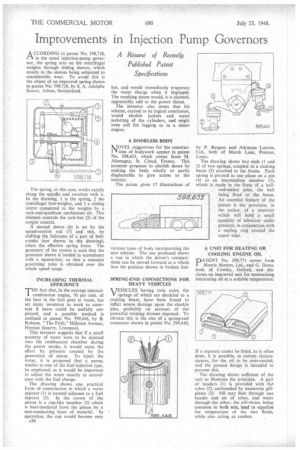
MOVEL suggestions for the construe' tion of bodywork appear in patent No. 598,633, which comes from M. Alamagny, St. Cloud, France. This inventor proposes to abolish doors by making the body wholly or partly displaceable to give access to the interior.
The patent gives 17 illustrations of various types of body incorporating the new scheme. The one produced shows a van in which the driver's compartment can be moved forward as a whole into the position shown in broken line.
SPRING-END CONNECTIONS FOR HEAVY VEHICLES
VEHICLES having twin axles, the springs of which are shackled to a rocking beam, have been found to inflict severe damage upon the shackle pins, probably on account of the powerful twisting stresses imposed. To obviate this is the aim of a spring-end connector shown in patent No. 599,410,
by P. Burgess and Atkinson Lorries, Ltd., both of Marsh Lane, Preston, Lancs.
The drawing shows two ends (1 and 2) of two springs, coupled to a rocking beam (3) attached to the frame. Each spring is pivoted in one plane on a pin (4) to an intermediate member (5), which is made in the form of a balland-socket joint, the ball being fixed to the beam. An essential feature of the patent is the provision, in the socket, of a reservoir which will hold a small quantity of lubricant under pressure, in conjunction with a sealing ring around the upperedge.
A UNIT FOR HEATING OR COOLING ENGINE OIL PATENT No. 598,771 comes from Morris Motors, Ltd. and a Dono, both of Cowley, Oxford, and disr closes an improved unit for maintaining lubricating oil at a suitable temperature.
If a separate cooler be fitted, as is often done, it is possible, in certain circumstances, for the oil to be over-cooled, and the present design is intended to prevent this.
The drawing shows sufficient of the unit to illustrate the principle. A pair of headers (1) is provided with flat tubes (2), surrounded by numerous gillplates (3). Oil may flow through one header and set of tubes, and water through the other; the cill-nlates, being common to both sets, tend to equalize the temperature of the two fluids, while also acting as coolers.