


Shaft-operated Servo Brake
Page 62
If you've noticed an error in this article please click here to report it so we can fix it.
A Resume of Patent Specifications That Have Recently Been Published
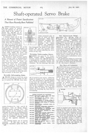
ASERVO braking system in which power is derived from the rotation of the propeller shaft is the subject of patent No., 467,184, by H. Leitner, Abbey House, Victoria Street, London, S.W.1.
A friction clutch (4) at the rear of the gearbox forms the servo-motor, which carries a small cable-winding drum. The cable from this is attached to one arm of a two-armed lever (5), which ultimately transmits the pull to the cross-shaft (6) of the brake system. The pedal operates an unequally balanced lever (2), theeupper end of which is connected to a directaction cable, whilst the lower end carries a cable attached to the operating finger (3) of the servo clutch.
lin, operation, pedal pressure applies direc,t braking until a predeterthined tension is reached in the upper cable ; alter this the lever (2) rocks and operates the servo motor. The changeover from direct to power-assisted braking is stated to be so gradual as to be imperceptible, a feature tending to aSsist precise judgment of braking force.. In case of power failure, a stoppiece (1) is provided to limit the rocking movement of the lever (2).
Reversible Self-energizing Brake.
ABRAKE design in which the shoes act as servo-motors forms the subject of patent No. 467,341, from Auto
motive Products Co., Ltd.. and E. B. Boughton, both of Brock House, Langharn Street, London, W.1. The chief feature of the scheme is that, although the shoes act as leading shoes —that is, tend to magnify the braking effort by moving with the drum—this action is reversible, working equally well in the opposite direction of rotation.
The drawing shows one of several methods. In this case, a pair of hydraulic expanders opens the shoes, B45 . whilst abutment pins (3 and 4) serve as fixed anchorages. With anticlockwise rotation the pistons (1) move, expanding the shoes
3 a against the abutments (4). A reversal of rota
tion transposes the duties to the other pistons (2) and the opposite abutments (3) without affecting the servo action in any way.
Preventing Trailer-coupling Chatcer.
BEA.RING the name R. W. Neate, 62, London Road, Kingston-onThames, patent No. 467,185 discloses a mounting for a trailer drawbar, the object being to eliminate chatter and vibration. In the drawing, the boss (2) is carried by the tractor, whilst the trailer is coupled to the towing-hook (1). The last-named is slidably guided in the boss (2) and pulls against the ccnipression of a spring (3). A second spring (4) is trapped on the opposite side of the abutment, and it is this feature that is stated to eliminate chatter by absorbing the force due to overrunning.
New Injectorctiozzle Design.
liDATENT No. 467,124, frond F. Deckel, 7-13 Waakirchnerstrasse, Munich, Germany, describes an improvement in the design of the fuel passages in injectors for oil engines. The drawing shows the arrangement applied to a nozzle of the open-end variety, in which the spray orifice is formed by a centrally Oierced disc. (2). Fuel arriving from the pipe-line passes down the hollow plug (1), through a cross-bore into an annular groove (4), thence down a helical groove (3) into a disc-shaped space immediately above the spray orifice.
The specification makes no statement as to the advantages of the design, an the patent is based upon the presence of the disc-shaped clearance.
New Heavy-oil Carburetter.
ALTHOUGH many attempts have, in the past, been made to construct a satisfactory heavy-oil vaporizer, there is .still considerable room for progress. Patent No. 467,089 describes an improved design for which the claim is made that it is the first successful method of its kind. The patentee is F. A. Kane, 17, Fairview Terrace, Derby, Connecticut, U.S.A.
The fuel is raised from the float chamber by suction, and is drawn through jet 2. A number of nested venturis, of progresively increasing diameters, forms the mixing tube;
which is supplied.with heated air from passage 3 and cold air from inlet 1, bothbeing throttled in unison. Each venturi has a slight clearance between it and its fellows, so that air stream4 are constantly impinging on the mixture as it travels towards the engine.
The successful action is stated to depend upon the creation of zones of low pressure about the gaps between the venturis ; these are claimed to vaporize fully the fuel globules. .