


Dewandre Invention
Page 72
If you've noticed an error in this article please click here to report it so we can fix it.
for Brakes and Steering Gears
AN ingenious invention is described in patent No. 306,518, by the Servo Frein Dewandre Societe Anonyme of Liege, Belgium. Although mainly intended for the mechanism employed for transmitting power to brakes, it is also described as being of .Use for the connections of steering gears. We have chosen the example of its application to steering gears to illustrate its principle, as in that form it is more readily understood.
The object of the invention is to provide a means for transmitting movement from such a part as a brake lever or a steering box to any component like a front axle where, through spring movement, the two parts are not at all times the same distance apart.
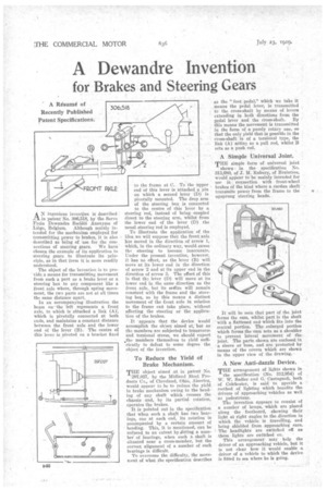
In an accompanying illustration the beam on the left represents a front axle, to which is attached a link (A), which is pivotally connected at both ends, and maintains a constant distance between the front axle and the lower end of the lever (B). The centre of this lever is pivoted on a bracket fixed
to the frame at C. To the upper , end Of this lever is attached a .pin on which a second lever (D) is pivotally mounted. The drop arm
of the steering box is connected to the centre of this lever by a steering rod, instead of being :coupled direct to the steering arm, whilst from the lower end of the lever (D) the usual steering rod is employed.
To illustrate the application of the ; idea we will suppose that the front axle . has moved in the direction of arrow 1, which, in the ordinary way, would, cause the steering to become inaccurate. Under the present invention, however. it has no effect, as the lever (B) will move at its lower end in the direction of arrow 2 and at its upper end in the direction of arrow 3. The effect of this is that th-2 fever (I)) will move at its lower end in the same direction as the front axle, but its eatre will remain constant with the frame and the steering box, so by this means a distinct movement of the front axle in relation to the frame cad take place, without affecting the steering or the application of the brakes.
It appears that the device Would accomplish the object aimed at; but as the members are subjected to transverse and torsional stress, we should expect .the members themselves to yield sufficiently to defeat to some degree the object of the invention.
To Reduce the Yield of Brake Mechanism.
THE object aimed .at in patent No.
297,027, by the Midland Steel Products Co., of Cleveland, Ohio, America, would appear to be to reduce the yield in brake mechanism owing to the bending of any shaft which crosses the chassis and, by its partial rotation, operates the brakes.
It is pointed out in the specification that when such a shaft has two bearings, one at each end, its rotation is accompanied by a certain amount of bending. This, it is mentioned, can be reduced to an extent by *fitting a number of bearings, when such a shaft is situated near a cross-member, but the correct alignment of a number of such bearings is difficult.
To overcome the difficulty, the movement of what the specification describes
as the "foot pedal," which we take it means the pedal lever, is transmitted to the cross-shaft by means of levers extending in both directions from the pedal lever and the cross-shaft. By this means the movement is transmitted in the form of a purely rotary one, so that the only yield that is possible in the cross-shaft is of a torsional type, the link (A) acting as a pull rod, whilst B acts as a push rod.
A Simple Universal Joint.
THE simple form of universal joint
shown in the specification No. 313,680, of J. M. Rubury, of Braintree, would appear to be mainly intended for use in connection with front-wheel brakes of the kind where a cardan shaft transmits power from the frame to the upsprung steering heads.
It will be seen that part of the joint forms the cam, whilst part is the shaft with a flattened end-which fits into the central portion. The enlarged portion which forms the earn acts as a shoulder ti prevent lateral movement of the. joint, The parts shown are enclosed in a sleeve or boss, and are protected by means of the covers which are shown in the upper view of the drawing.
A New. Anti-dazzle Device.
THE arrangement of lights shown in the specification (No. 312,954) of W. W. Sadler and G. Casts gnoli, both of Colchester, is said to provide a " method of lighting which benefits the drivers of approaching vehicles as well as pedestrians. Tim invention appears to consist of a number of lamps, which are placed along the footboard, showing their light at right angles to the direction in which the vehicle is travelling, and being shielded from approaching cars. The headlights are switched off as these lights are switched on. •
This arrangement may help the driver of an approaching vehicle, but it is not clear how it would enable a driver of a vehicle to which the device is fitted to see where he is going.