


Patents Completed.
Page 20
If you've noticed an error in this article please click here to report it so we can fix it.
GREASE CUP.. — Rotherham. — No. 24,565, dated 6th November, 1907.—This invention relates to a grease cup particularly designed to prevent itself becoming dislodged from the stem by vibration. The grease cup (A) is screwed on to the Stem (E) in the usual manner and it is provided with a cup member .(B) which is screwed into the top of the cup. The cup Member supports a spindle (C) having ribs which engage recesses in a disc (D) secured to the stem (E) in such a manner that the spindle (C) is free to slide, but is prevented from rotating. The springs (G) are secured to the spindle (C) and are adapted to engage with recesses (F) in the grease cup (A). These springs, although permitting the grease cup to be turned by hand, prevent any possibility of its becoming loose by vibration.
INTERNAT,-COMBUSTION ENGINE. —Core.—No. 3,978, dated 21st February, 1908.—This invention relates to internalcombustion engines having mechanicallyoperated inlet valves and in which a previously compressed charge is introduced into the cylinder for the purpose of starting the engine. The air compressor (h) supplies air to a reservoir (k) where it is conveyed, by means of a pipe (1), past a stop valve (a) into the carburetter from whence it flows into the inlet chamber (0.). In order to prevent the inlet valve (a) being operated by the compressed charge, the spindle (al) is guided by a piston (c) working in the cylinder casting. The spindle (al) of the inlet valve is pro videcl with a collar (e); a spring (d) is interposed between this collar and the piston (c). The piston is provided with a flange (cl) to prevent it being forced too far into the inlet Chamber (Li) by the spring (d). The inlet valve (a) is operated at the proper time by the cam (J) on the half-time shaft (g). It will be seen that the compressed charge will exert an equal pressure on both the valve (a) and piston (c), sb that the latter will be balanced and thus will prevent.the valve being operated, at the wrong moment. ROTARY PUMP.—Tod.—No. 7,878, dated 9th April, 1908.—In pumps of the rotary type in which toothed wheels— driven by a shaft or shafts—are disposed within a chamber, the glands form a source of leakage, and, in consequence, the wear and tear on the shafts is excessive. According to this invention it is proposed to prevent leakage past the gland (b) by providing a recess (d) in the bearing. This recess is connected with the main chamber by means of a passage (k) terminating in an orifice (f) in the wall of the pump chamber. This orifice opens into the pump chamber immediately below the line (x) joining the centres of rotation of the toothed pump wheels. As the teeth of the pump wheels approach each other they gradually displace liquid between the tooth of one wheel and a space between adjacent teeth of the other, with the exceptiOp of a small quantity occupying the clearance space, and, when the teeth pass the line {x), they gradually recede from each other and increase the clearance space between the teeth, thus causing a partial vacuum as they pass the orifice (I) so that liquid in the recess (37:( will be drawn through the passage (h) into the pump chamber again.
CI,EA NI NG 1) EVIC E.---Martin.—No. 13,204, dated 6th March, 1907.—This invention relates to a device for cleaning the interior of steam-boiler, gauge-glass cocks. The device comprises a plug (0, screw-threaded at one end (c1), and provided with a nut (d). The plug is bored to receive a spindle (a) .a.4d is. provided with a stuffing box (4) so as to make a stearn-tight joint between the plug and the spindle (a). The spindle is provided with a hand wheel (h) at one end, and the other end is made of square section (a2) terminating in a point .(a1). The plug in use is screwed into the boiler fitting by means of the nut (d) and screw thread (c1); and the spindle lc) is advanced into the water so as to remove the dirt accumulated therein.
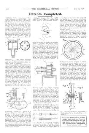
ROTARY COOLER.—Megevet.—No. 23,637, dated 25th October, 1907.—This invention relates to a water-cooling system in which the hot water from the cylinder jacket is cooled by being conveyed through the vanes of a fan. A series of
hollow vanes (c) are mounted on a boss (h) which, in turn, is flexibly mounted on a stationary axle (7). This axle is provided with a channel (g) communicating, at one end, with a pump (a) ; it is adapted to register with a second channel (m) in the hub (h). Another channel (h) is also provided in the axle (7), and this registers with a channel (n) connected to the outer ends of the vanes (c). The hot water from the cylinder jackets is forced by the pump (i) through the channel (g) into the vanes where it is cooled and returned to the cylinder jackets by the tube (e) and channel (h). The hub (b) is driven
by a gut pulley (1) which is connected to a
similar pulley on the spindle (z) of the pump (i).