


Keeping up the charge
Page 34
Page 35
If you've noticed an error in this article please click here to report it so we can fix it.
VEHICLE LIGHTING and starting systems have already been covered in this series, and this week it is the turn of the charg ing system. As previously, the emphasis is on light commercial vehicles, and in this case those fitted with de as opposed to ac charging systems.
Hints on the type of test equipment and correct method of fault diagnosis have once again been supplied by the tachnical service department of Joseph Lucas (Sales and Service) Ltd. But before getting down to brass tacks it is as well to be acquainted with what we are dealing with.
There are two methods of charging the battery, known respectively as the ac and dc charging systems. Actually, the two Fundamentally, the current generated is ac (alternating current) in each case, but as this type of current is unsuitable for charging the battery, the output is rectified to dc (direct current). The alternator output is rectified by means of a diode rectifier, mounted inside the alternator. The dynamo output is rectified by means of the commutator, which is mounted on the armature shaft and rotates with it.
A characteristic of the dynamo is that its output increases directly with speed, so a control box is necessary to keep the output within safe limits, especially as the dynamo speed may vary between 600 and 10,000 rev/min. There are two types of control box used, the compensated voltage and 'the current voltage. The compensated voltage control box consists of two bobbins : the cutout and the voltage regulator.
The cutout is an electrically operated relay, which prevents the battery from discharging through the generating windings, when the dynamo is stationary or the output voltage is less than the battery terminal voltage. The voltage regulator ensures that the output voltage is kept within predetermined limits. The output tapers off, as the battery becomes charged, until only 2-3 amps are delivered to the battery.
As the number of electrical appliances on vehicles increased — including heaters and demisters — there was a need for a more positive method of control, so the current voltage control box was introduced. This enables the dynamo to deliver its maximum output for a longer period, when the battery is discharged. The current voltage regulator box has three bobbins. In addition to the cutout and the voltage regulator, it has a current regulator, which controls the dynamo output for the first stage of the charging period, until it reaches its current setting. The voltage regulator then takes over, and the dynamo output tapers off, as the battery becomes charged, until only 1-2 amps are supplied to the battery.
We should emphasise that both types of control box have been accurately set during production, and do not normally require any further attention in service. The contacts may need cleaning after the control box has been in use for a considerable period, but the regulator settings should not be adjusted until the entire charging system has been checked. Do not forget that a fault in the battery, the dynamo or the connecting cables would point to a faulty control box.
Test equipment
Two good quality meters (preferably Industrial Grade) are required: dc voltmeter, scale 0-20V; dc ammeter, scale 5-0-40 amp.
The other instruments required are: Hydrometer; RB340 adjusting tool (part no 54381742); jumper lead.
Control box bobbins There is an easy way to identify the control box bobbins. Remove the control box cover, and point the terminals towards you. Then, the bobbin on the left is the voltage regulator, and the bobbin on the right is the cutout. The centre bobbin (on 3-bobbin control boxes) is the current regulator.
Test procedure
1. Battery If there is any reason to suspect the charging system, check that the battery is in good condition end sufficiently charged. Make a preliminary check of the battery connections. Ensure they •are clean and tight. Then use the hydrometer to determine the state of battery charge. All cell readings should be at least 1.230, indicating that the battery is at least 70 per cent charged.
If the cell readings are lower than 1.230, the battery should be recharged by means of a battery charger (not, of course, a trickle charger).
2. Fan Belt If the fan belt is loose or slipping it will affect the rate of battery charging, so the belt tension must be checked periodically. There must be just in (6mm) deflection, when light finger pressure is applied to the longest run between the two pulleys.
FIG. 1
3. Connections Do not forget that loose or bad earth connections are often the cause of charging failure. Ensure that all connections are in position, making good electrical contact. Any dirty connections must be cleaned.
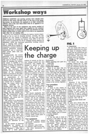
4. Voltage at "D" terminal of control box To check the leads and dynamo, remove the "D" lead from the control box, and connect the voltmeter between the "D" lead and earth. The engine should be slowly increased to 1500rev/min (or approx 25mph in top gear), when the voltmeter should read 1.5 to 3V. If the voltmeter reading is satisfactory, the field circuit and cables should then be tested. (Test 5).
However, if the voltmeter reading is zero, there is probably an open-circuit " D " lead or a faulty dynamo. On the other hand, if the voltage increases with speed, there is probably a short circuit between the "D" and "F" leads. In either case, it will be necessary to check the voltage at the "D" terminal. (See Test 6).
5. Dynamo field circuit and cables If tests have shown that the "D" lead to the control box is satisfactory, it will be necessary to check the dynamo "F" lead. Remove the "F" lead from the control box and, with the voltmeter still connected as for the previous test connect the ammeter between the dynamo "D" and "F" leads. Then, thE engine is started, and slowly accelerated, until the voltmeter reads 12V. The ammeter shoulc then read 2-2.5amp. If the am meter reading is satisfactory you should proceed to Test 8 If, however, there is a zerc ammeter reading and a by voltage reading, it indicates an open circuit "F" lead or a fault in the dynamo. It will, therefore, be necessary to test the dynamo field circuit (Test 7), in order to locate the fault. NOTE: Ensure "I)" and "F" leads are re-connected to the correct terminals. Otherwise, the contact points of the control box may be seriously damaged.
6. Voltage at "D" of dynamo In this test, we are .checking the continuity of the armature circuit, that is, the electrical path through the brushes, commutator and 'armature windings. The voltmeter is still connected between "D" terminal and earth (see fig 1). The engine is started and slowly accelerated to approximately 1,500rev/min. The voltmeter should then read 1.5 to 3V, indicating that the brushes are making contact with the commutator and that the brushgear and armature windings are serviceable.
If, however, the voltmeter reads zero, the dynamo must be removed for bench examination. This test is performed when the voltage reading at the control box "D" terminal is unsatisfactory. So that, if this test produces a correct voltage reading, either the "D" lead is open-circuit, or there is a short circuit between the "D" and "F" leads. in either case, the fault must be traced by checking the field circuit (Test 5).
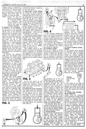
7. Dynamo field circuit Next the field circuit should be tested, while the voltmeter is still connected between the dynamo "D" terminal and earth, an ammeter should be connected between "1)" and "F" (see fig 2). The engine speed should be slowly increased, until the voltmeter registers battery volts (12V). The ammeter should then read approximately 2-2.5amp. A higher reading would indicate an internal short circuit, while a zero reading would indicate an open-circuit field coil. Consequently, the dynamo should be
FIG. 2
removed for detailed inspection on the test bench.
8. Open-circuit voltage setting To check the voltage setting, the current loading should be removed from the control box, by detaching the battery leads from the "A" and "Al" terminals (on RB106 Control Box) or the "B" terminals (on RB340 Control Box), and joining them together. A voltmeter is connected between terminal "D" on the control box, and a good earth on the engine block. Start the engine, and accelerate to approximately 3,000/rev/min (or 45-mph in top gear).
The voltmeter reading should be within the following limits : Control box model RB106— voltage setting: 16.0-16.5. Control box model RB340—voltage setting: 14.5-15.5 (if setting is 0.5V above or below these limits in the case of RB340, reset to nearest limit).
The voltage setting is 'adjusted by turning the adjusting screw : clockwise (to increase the voltage) and anti-clockwise (to reduce it). A special adjusting tool (Part No 54381742) is required for the RB340 Control Box.
FIG. 3
If the unit cannot be set within the specified limits by turning the adjusting screw, check the earth connection of the control box.
9. Control box earth connection The earth connection between the control box and the body of the vehicle must be clean and tight. To check the earth connection, connect the jumper lead between control box "E" terminal and a good earth point on the engine or vehicle body, and then repeat the previous test (Test 8).
FIG. 4
If the voltmeter reading can now be set within the specified limits, the original earth connection is faulty and should be re-made. Ensure there is a good metal-to-metal contact.
If, however, the reading is still outside the limits and cannot be adjusted, the control box should be replaced.
10. Cutting-in voltage This is the voltage at which the battery is connected to the dynamo, enabling the charging current to flow into the battery. An ammeter is connected between the leads, which have been removed, and the control box terminal, "A" or "B", on RB106 and RB340, respectively. The ammeter should still be connected between the "D" terminal and earth. The headlamps are then switched on, and the engine is started and slowly accelerated. When the cutout contacts close and the voltmeter needle "flicks" back, the voltmeter should register between 12.5 and 1345. If the reading is outside these limits, the cutout should be adjusted by means of the adjusting screw. (The special tool is required for adjusting RB340).
The ammeter shows that the current is flowing into the battery, the actual reading depends on the state of battery charge and the electrical loading.
11. Reverse current The cutout also disconnects the dynamo from the battery, when the dynamo stops charging, and the output voltage falls below that of the battery. It also prevents the battery from discharging through the dynamo, when the vehicle is stationary. To check the reverse current, both the ammeter and the voltmeter should be connected, as for the previous test. As the engine speed is gradually reduced, the ammeter needle should fall, until it indicates a discharge (or reverse) current of 2-7amp. The ammeter needle should return to zero, when the cutout contacts open.
12. Current regulator setting (RB340) As the dynamo must develop its maximum output, irrespective of the state of battery charge, the voltage regulator must be made inoperative. This can be done by shorting out the regulator contacts by means of a bulldog clip (see fig 3). The dynamo is then run at charging speed, approximately 4,500rev/ min (about 45 mph in top gear). The ammeter should be connected between the "B" leads and the control box "B" terminal. The current regulator should be set, as follows : If the reading is too high or too low, the setting should be adjusted by means of the adjusting screw at the back of the frame. The special tool will be required.
13. Voltage drop: charging circuit supply line Finally, check the continuity of the insulated or supply lines. The lead is removed from the dynamo "D" terminal, and an ammeter is connected between the "D" lead and the "D" terminal on the dynamo, while a voltmeter is connected between the "D" lead terminal and the battery terminal on the starter solenoid (see fig 4). The engine is started 'and accelerated, until the 'ammeter registers 10amp. The voltmeter reading should not exceed 0.75. A higher voltage reading probably indicates dirty or 'loose connections in the insulated or supply line.
These tests will identify 90 per cent of system faults.