


The compression ignition engine, 6
Page 67
If you've noticed an error in this article please click here to report it so we can fix it.
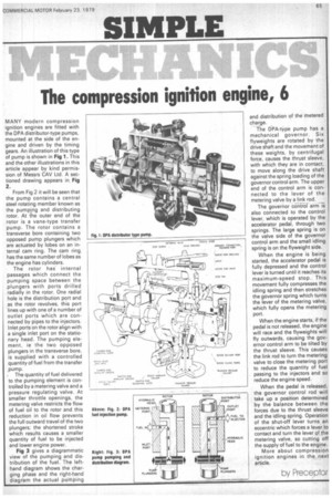
MANY modern compression ignition engines are fitted with the DPA distributor-type pumps, mounted at the side of the engine and driven by the timing gears. An illustration of this type of pump is shown in Fig 1. This and the other illustrations in this article appear by kind permission of Messrs CAV Ltd. A sectioned drawing appears in Fig 2 From Fig 2 it will be seen that the pump contains a central steel rotating member known as the pumping and distributing rotor. At the outer end of the rotor is a vane-type transfer pump. The rotor contains a transverse bore containing two opposed pump plungers which are actuated by lobes on an internal cam ring. The cam ring has the same number of lobes as the engine has cylinders.
The rotor has internal passages which connect the pumping space between the plungers with ports drilled radially in the rotor. One radial hole is the distribution port and as the rotor revolves, this port lines up with one of a number of outlet ports which are connected by pipes to the injectors. Inlet ports on the rotor align with a single inlet port on the stationary head. The pumping element, ie the two opposed plungers in the transverse bore, is supplied with a controlled quantity of fuel from the transfer ,pump.
• The quantity of fuel delivered to the pumping element is controlled by a metering valve and a pressure regulating valve. At smaller throttle openings, the metering valve restricts the flow of fuel oil to the rotor and this reduction in oil flow prevents the full outward travel of the two plungers; the shortened stroke which results causes a smaller quantity of fuel to be injected and lower engine power.
Fig 3 gives a diagrammatic view of the pumping and distribution of the fuel. The lefthand diagram shows the charging phase and the right-hand diagram the actual pumping and distribution of the metered charge.
The DPA-type pump has a mechanical governor. Six flyweights are rotated by the drive shaft and the movement of these weights, by centrifugal force, causes the thrust sleeve, with which they are in contact, to move along the drive shaft against the spring loading of the governor control arm. The upper end of the control arm is connected to the lever of the metering valve by a link rod.
The governor co-nirof arm is also connected to the control lever, which is operated by the accelerator pedal, through two springs. The large spring is on the valve side of the governor control arm and the small idling spring is on the flyweight side.
When the engine is being started, the accelerator pedal is fully depressed and the control lever is turned until it reaches its maximum-speed stop. This movement fully compresses the idling spring and then stretches the governor spring which turns the lever of the metering valve, which fully opens the metering port.
When the engine starts, if the pedal is not released, the engine will race and the flyweights will fly outwards, causing the governor control arm to be tilted by the thrust sleeve. This causes the link rod to turn the metering valve to close the metering port to reduce the quantity of fuel passing to the injectors and so reduce the engine speed.
When the pedal is released, the governor control rod will take up a position determined by the balance between the forces due to the thrust sleeve and the idling spring. Operation of the shut-off lever turns an eccentric which forces a lever to contact and turn the lever of the metering valve, so cutting off the supply of fuel to the engine.
More about compression ignition engines in the next article.
by Prece otor