


A Simple Gearbox Power Take-off
Page 58
If you've noticed an error in this article please click here to report it so we can fix it.
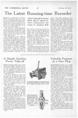
OUR attention is drawn by S. Smith and Sons (Motor Accessories), Ltd., Cricklewood Works, London, N.W.2, to a new standardized power take-off for the gearboxes of practically all makes of British and American vehicle. The accompanying illustration shows the general layout.
The unit is brought into mesh with the gears in the gearbox when it is required, but when not in use the unit is not revolving. The reduction ratio can be made to suit the gearbox, and varies between 1 to 1 and 2 to 1, the direction of rotation being in nearly every case opposite to that of the engine crankshaft.
The driven shaft of the power takeoff terminates in a flange, which is arranged to fit the Hardy-Spicer universal coupling, No 100k. Complete shafts can be supplied if the length between flange faces be snecified. Alternatively, the unit can be purchased without the driving flange. The maximum power which the unit is intended to transmit is 4 b.h.p.
The power take-off is useful for driving such auxiliaries as dynamos, suction pumps, tipping gears, air compressors, etc. Where a propeller shaft is coupled to the drive unit it is sometimes necessary to provide a support bearing for the tail end of the shaft, but bearings of this kind are not supplied except by arrangement, because conditions of fitting vary greatly.
u44