


GOOD FEATURES in a NE
Page 46
Page 47
Page 48
If you've noticed an error in this article please click here to report it so we can fix it.
ROTARY-VALVE ENGINE
The McLaren-Lewis Petrol Engine which Incorporates a Design of Rotary Valve Possessing Certain Entirely New Features Performance on Road and Bench Affords Convincing Evidence in Justification of the Claims for Durability and Efficiency
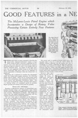
THERE have been so many attempts to develop the rotary-valve, internal-combustion engine, a type which seems to hold a powerful magnetism for inventors, and so few that have encountered any measure of success, that it is hard to view a new design with an entirely unbiased mind. An engine of this type, however, has now appeared which seems to be free from those weaknesses that have come to be regarded as almost impossible to eliminate when the rotary-valve is employed.
Digressing for a moment to consider the advantages which the rotary-valve engine possesses, the following points come to mind. There are no reciprocating parts in the valve mechanism, with consequent elimination of inertia forces and attendant mechanical noise. The valve ports are positively closed, and thus valve bounce —a limiting factor of crankshaft speed—is avoided. Rapid opening and closing of the ports are possible.
Rotary-valve Advantages.
Freedom is afforded the designer in determining combustion-chamber shape and compression ratio, which should mean high power-to-weight ratio, smooth running and economy. Manufacture is simple. The design involves only the easiest machining operations, and the castings needed are by no means elaborate.
The new valve gear is described as the McLarenLewis and was designed and constructed in Australia by Mr. H. S. McLaren, Union Street, New Brighton, Victoria, Australia. The present headquarters of the inventor, who is now in this country, are G.N., Ltd., 300, Balham High Road, London, S.W.17. We recently inspected the invention on a converted Peugeot six-litre, six-cylindered engine installed in a 12-year-old car of the same make, and obtained some knowledge of its performance in a short run on the road.
The power unit is capable of about 3,000 r.p.m„ trie top-gear ratio is 3i to 1, and the speed which we attained without difficulty was 85 m.p.h., but this is admittedly no definite indication of what the performance of the unit would be in a lorry. We are informed, however, that the vehicle with this engine installed has covered 14,000 miles, consuming petrol at the rate of 15 m.p.g., and a close examination of the valve and bearing surfaces reveals scarcely a trace of wear.
Bench tests have shown that the unit develops 83 b.h.p. at 2,300 r.p.m. This figure was obtained with a single Zenith carburetter; a higher output has since been developed with twin Solex instruments.
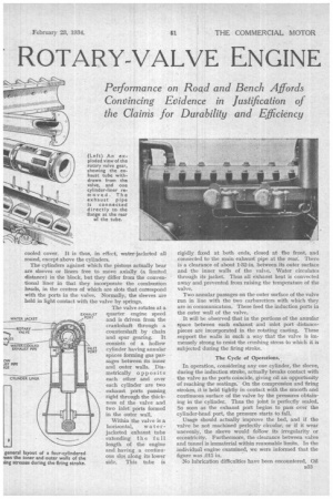
Reference to the accompanying drawings will enable the simple construction of the engine to be understood. The rotary Valve, which is made of cast iron, is disposed longitudinally along the top of the cylinder block, being supported by the tops of the cylinders, which are shaped to form segments of the walls of the tunnel in which it revolves, and the detachable water cooled cover. It is thus, in effect, water-jacketed all round, except above the cylinders.
The cylinders against which the pistons actually bear are sleeves or liners free to move axially (a limited distance) in the block, but they differ from the conventional liner in that they incorporate the combustion heads, in the centres of which are slots that correspond with the ports in the valve. Normally, the sleeves are held in light contact with the valve by springs.
The valve rotates at a quarter engine speed and is driven from the crankshaft through a countershaft by chain and spur gearing. It consists of a hollow cylinder having annular spaces forming gas passages between its inner and outer walls. Diametrically opposite each other and over each cylinder are two exhaust ports passing. right through the thickness of the valve and two inlet ports formed in the outer wall.
Within the valve is a horizontal, waterjacketed exhaust tube extending the full length of the engine and having a continuous slot along its lower side. This tube is
rigidly fixed at both ends, closed at the front, and connected to the main exhaust pipe at the rear. There is a clearance of about 1-32-in, between its outer surface and the inner walls of the value. Wafer circulates through its jacket. Thus all exhaust heat is convected away and prevented from raising the temperature of the valve.
Two annular passages on the outer surface of the valve run in line with the two carburetters with which they are in communication. These feed the induction ports in the outer wall of the valve.
It will be observed that in the portions of the annular space between each exhaust and inlet port distancepieces are incorporated in the rotating casting. These support the walls in such a way that the valve is immensely strong to resist the crushing stress to which it is subjected during the firing stroke.
The Cycle of Operations.
In operation, considering any one cylinder, the sleeve, during the induction stroke, actually breaks contact with the valve as the ports coincide, giving oil an opportunity of reaching the seatings. On the compression and firing strokes, it is held tightly in contact with the smooth and continuous surface of the valve by the pressures obtaining in the cylinder. Thus the joint is perfectly sealed. So soon as the exhaust port begins to pass over the cylinder-head port, the pressure starts to fall.
Usage should actually improve the bed, and if the valve be not machined perfectly circular, or if it wear unevenly, the sleeve would follow its irregularity or eccentricity. Furthermore, the clearance between valve and tunnel is immaterial within reasonable limits. In the individual engine examined, we were informed that the figure was .015 in.
No lubrication difficulties have been encountered. Oil B33
reaches the valve by way of the clearance between the liners or sleeves and the walls of the cylinders proper, flow being stimulated by the vacuum created in the head during the induction stroke, and, of course, by the axial movement (which amounts to little more than vibration) of the sleeves. It is supplemented by the addition to the petrol of lubricant in the proportion of one part to 100.
As a practical test for overheating of certain parts of the mechanism, Mr. McLaren has lined with white metal the top half of the valve bearing, and has faced the sleeves with the same material. No signs of fusion are detectable. We understand that this white metal is in no way necessary, cast iron against cast iron having proved entirely satisfactory for bearing surfaces. It should be pointed out that the design eliminates hot spots and uneven heating ; consequently, high-compression ratios can be successfully employed and there is no distortion.
A Proof of Mechanical Efficiency.
As a precaution against damage that might be caused by seizure of the valve, this is driven from the large pinion by only two fin, bolts, each axially drilled with a 3-32-in. hole. That these have remained intact may be accepted as evidence that the valve bearing surfaces are neither overloaded per unit of area nor inadequately lubricated, and that the valve is properly protected from overheating. In this respect the constant circulation through it of cool gas supplements the water jackets.
With the design and setting of the ports employed in the model under consideration and the use of the twin Solex carburetters, irregular firing when ticking over is pronounced, but when under light load the firing is perfectly regular and the running smooth throughout the complete range of speeds.
There is, too, a momentary hesitation noticeable on the road at initial throttle openings. Apart from this, acceleration is excellent. The port setting is such that there is no overlap of inlet and exhaust.
Dismantling a Matter of Simplicity.
After our trial on the road the head was dismantled. One man performed this operation in under 30 minutes. When the cover has been removed the valve can be lifted out and the sleeves easily withdrawn by hand. The latter can as easily be replaced, their deeply chamfered bases squaring up the piston and serving as a lead for the piston rings.
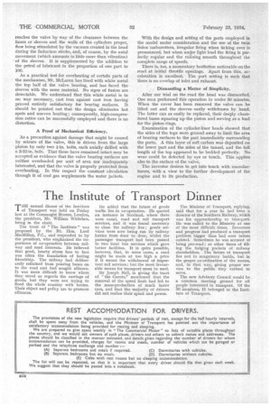
Examination of the cylinder-liner heads showed that the sides of the tops were ground away to limit the area of bearing surfaces to the part immediately surrounding the ports. A thin layer of soft carbon was deposited on the lower part and the sides of the tunnel, and the full length of the top appeared to be bedded perfectly. Nowear could be detected by eye or touch. This applies also to the surface of the valve.
The inventor desires to get into touch with manufacturers, with a view to the further development of the engine and to its production.