


An Automatically Adjusted Hydraulic Brake
Page 60
If you've noticed an error in this article please click here to report it so we can fix it.
A Re'sume' of Recently Published Patent Specifications
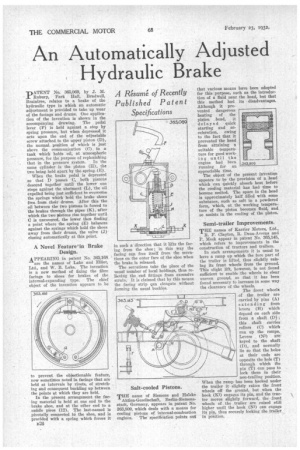
"nATENT No. 365,069, by J. M. ..E Rubury, Park Hall, Bradwell, Braintree, relates to a brake of the hydraulic type in which an automatic adjustment is provided to take up wear of the facings and drums. One application of the invention is shown in the accompanying drawing. The pedal lever (F) is held against a stop by spring pressure, but when depressed it acts upon the end of the adjustable screw attached to the upper piston (D), the normal position of which is just above the communication (0) to a tank which holds oil, at atmospheric pressure, for the purpose of replenishing
that in the pressure system. In the same cylinder is the piston (H), the two being held ,apart by the spring (E).
When the brake pedal is depressed so that D passes C, both pistons descend together until the lower one stops against the abutment (L), the oil expelled being just sufficient to overcome the springs which hold the brake shoes free from their drums. After this the oil between the two pistons is forced to the brakes through the pipes (K), after which the two yiistous rise together until C is uncovered, the lower then finding a point where the spring (E) balances against the springs which hold the shoes away from their drums, the valve (J) closing automatically at this point.
A Novel Feature in Brake Design.
APPEARING in patent No. 365,168 are the names of Lake and Elliot, Ltd., and W. B. Lake. The invention is a new method of fixing the fibre facings to shoes for brakes of the internal-expanding type. The chief object of the invention appears to be to prevent the objectionable feature, now sometimes noted in facings that are held at intervals by rivets, of stretching and consequent buckling up between the points at which they are held.
In the present arrangement the facing material is held at one end to the brake shoe, and at the other end to a saddle piece (12). The last-named is pivotally connected to the shoe, and is provided with a spring which forces it 1326 in such a direction that it lifts the facing from the shoe; in this way the facing can free itself from the serrations on the outer face of the shoe when the brake is released.
The serrations take the place of the usual number of local holdings, thus relieving the end fittings from excessive strain. It is claimed that by this means the facing strip can elongate without forming the usual buckles.
Salt-cooled Pistons.
THE" name of Siemens and Halske
Aktien-Geselischaft, Berlin-Siemensstadt, Germany, appears in patent No. 363,809, which deals with a means for cooling pistons of internal-combustion engines. The specification points out that various means have been adopted for this purpose, such as the introduction of a fluid near the head, but that this method had its disadvantages. Although it prevented dangerous heating of the piston bead, it delayed quick starting and acceleration, owing to the fact that it prevented the head from attaining a suitable temperature for good working, until the engine had been running for an appreciable time. The object of the present invention appears to be the provision of a head which can quickly absorb heat before the cooling material has had time to become melted. The space in the head is approximately half filled with some substance, such as salt in a powdered form, which, at the working temperature of the piston becomes fluid, and so assists in the cooling of the piston.
T.'r411111111111%;?..4: ".145 '&.s1 Semi-trailer Improvements.
THE names of Karrier Motors, Ltd.,
R. F. Clayton, R. Dean-Averns and P. Meek appear in patent No. 365,145, which refers to improvements in the construction of tractors and trailers.
In such arrangements it is usual to have a ramp up which the fore part of the trailer is lifted, thus slightly raising its front wheels from the ground. This slight lift, however, is not found sufficient to enable the wheels to clear uneven ground, so that it has been found necessary to increase in some way the clearance of the wheels.
The front wheels of the trailer are carried by pins (A) extending from levers (H) which depend on each side from a shaft (D) ; this shaft carries rollers (C) which run up the ramps. Levers (N3) arekeyed to the shaft (D), and normally lie so that the holes at their ends are opposite the bole (T) through which the pin (T) can pass to lock them in their non-trailing position. When the ramp has been backed under the trailer it slightly raises the front wheels off the ground, but when the hook (K1) engages its pin, and the tractor moves slightly forward, the front wheels of the trailer are raised still higher until the hook (Ni) can engage
its pin, thus securely locking the trailer . , in pi:laid/in.