


A HYDRAULIC CLUTCH.
Page 30
If you've noticed an error in this article please click here to report it so we can fix it.
A Résumé of Recently Published Patent Specifications.
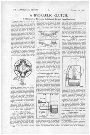
"Ls4 DMOND MOGLIA and the Anglofll Continental Export Co., in specification No. 246,007, show a form of hydraulic clutch which should permit of a, very gradual take up of the power transmitted from engine to the transmission.' It is the opinion of some enginee.rs that the adoption of a' clutch of this class, working in conjunction with another clutch which will permit of frictionless disengagement for changing gears, would be a step towards perfection in a. commercial vehicle. Four radial 'cylinders Are arranged round a crank. Each of these cylinders is provided with a non-return valve at A, and a sleeve which closes ports at B, which are allshown closed. The two members which the clutch unites are composed of the casing forming the cylinders on the mie part and the crank on the other part.
So long as the ports are not covered by the sleeves (B), fluid can enter and leave the cylinder freely at each stroke caused by the revolving of the crank in relation to the cylinders, but, as the ports are gradually closed, the friction of the fluid increases until a complete engagement is obtained. The method of opening and closing the sleeve valves is by means of a sliding collar on the shaft which operates a member with an angular slot, as shown diagrammatically in the lower view. As the ports . are closed by means of sliding action it will be seen that they have no tendency, to open automatically or to resist being closed.
As shown, there would always be an appreciable lack of balance in the pistons and a one-sided pressure in the bearingp which might result in eccentricity. Two throws to the crank set at 180 degrees would obviate this.
A Four-wheeled Bogie.
HENRY TAINSH (of the Caledon Motor Car Co., Ltd.), in specification No. 245,844, describes the arrangement of his six-wheeler, which has already been dealt with in this journal. /It will be seen that in this arrangement, the leading and following axles are connected by balanced members which are pivotally mounted near the centres of the half-elliptical springs. These springs are shackled to the frame at both ends and are located by means of radius rods as shown. Each axle is driven by means of worm and worm wheel. The cardan shaft which con iects the two worm shafts is provide with universal joints at both ends, one of which is of the sliding type. The lower view shows the means provided to prevent rotary movement of either axle casing around its own centre.
Projecting from each casing of the worm wheels are two lugs which support vertical pins forming pivotal connections between the two casings. Two members connect these lugs, one sliding and pivoting in the other. It will be seen from this that the only function these members are called upon to perform is the prevention of independent rotary movement of the casings, which in all other directions are free.
A Pressure-actuated Carburetter.
A. CARBURETTER which acts inde pendently of the depression in the inlet pipe is shown in the specification (No. 219,020) of J. A. Borel, of Haute Savoie, France. In this carburetter pressure is obtained from an air compressor, or other means, and is led by the pipe shown through a special throttle to a jet which induces petrol to flow from the jet pipe leading from the main supply, the action being similar to ,leit of the well-known scent spray. A choke is arranged as shown on the left, which is just sufficient to set up enough depression to cause the spray to be drawn up to the engine. The main throttle, which regulates the supply -of air, is coupled with the throttle of the pressure
pipe. The suction pipe .which conveys the petrol to the spray terminates in a hollow Which is slightly below the petrol level and is consequently always supplied with fuel.
The inventor claims that there is no obstruction in front of the spray, so that a constant uninterrupted supply of fuel and air can enter the cylinder even when the crankshaft is revolving slowly.
Relating to the Lubricating of Engines.
WE are reminded in specification
No. 245,956, by G. T. Smith-Clarke, that in ordinary circumstances, when an engine is started up, particularly in cold weather, several minutes may elapse before an adequate supply cf oil reaches the cylinder walls. This may be due to the sluggish movement of the oil through the pipe's, during which time damage might be done to various parts of -the engine. He takes advantage of the increased pressure of oil, set up by the resistance due to sluggishness in the pipes leading to the bearings of the crankshaft, to open a valve which enables a supply of oil to flow into troughs Situated under the big-ends. As the oil, gradually warms up to its work, and the pressure consequently decreases, the, spring valve closes and the oil circulates: to the bearings and through the drilled crankshaft, to the big-ends ; then the troughs come out of action.
The idea is an ingenious one, but we have seen such good results obtained from properly designed trough lubrication that we should think it would be as well to let them continue to do the, work and to save drilling the crankshaft.
A Governor for Use with Air Compressors. .
THE Ingersoll-Rand Co. of America, A in specification No. 245,830, describe a form of governor that is particularly useful _for those internal-combustion engines which are employed for driving air compressors.
In the governor shown centrifugal weights are employed, but a cylinder and piston operated by the pressure of air in the container assist in the governing,