


A GAS PRODUCER USING WOOD AS FUEL.
Page 11
Page 12
If you've noticed an error in this article please click here to report it so we can fix it.
This Equipment has been Developed for the French Military Authorities, for Use in the Colonies where Charcoal may Not be Readily Procurable.
TIlE obvieus necessity of being able. I_ to equip mechanically propelled vehicles to operate on other than liquid feels has for a long time been realized by manufacturers in general, and has frequently been discussed in the columns of Vie Commercial Motor, for it is keenly appreciated that the scope of the motor lorry would be considerably increased were it possible for it to be phipped to out-of-the-way corners of the Aini)P, where petrol is both difficult to obtain and prohibitive in price, the lorry being fitted with a means by which locally produced fuels could be used. The most satisfactory solution appears to be the use of producer-gas, and for this reason alone the trials which have recently been carried out in France under the auspices of thd military authorities should, as we have said, be of great interest to all concerned in the development of overseas trade.
Theft trials, it will be remembered, consisted of a run totalling some 1,325 miles in length over all sorts and Conditions of road throughout France, these trials being followea by further bench tests of the engines and the different ystems entered.
Fuller particulars are now available concerning the four Bernet vehicles which were entered. They were two :15-ewt. lorries and two 5-ton lorries, all !)cilig fitted with the Berliet-Imbert producer-gas plants, which have been
subjected to continual and arduous trial for the past two years.
The general objection to most producer-gas plants is that whilst providing an alternative to petrol as a fuel, they usually require some special fuel themselves, such as charcoal or similar products. In the Berliet-Imbert system this is unnecessary, the fuel used being ordinary wood cut into small pieces. . The fuel supply, therefore, for this plant can be obtained practically anywhere in the world. The installe-don comprises three elements: the generator in which the wood is burnt and the gas generated, the purifier and
the mixer. The functions of these three elements are described in the following paragraphs.
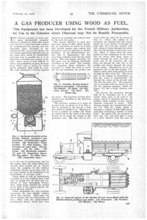
The generator consists of a drum of pressed steel, as shown at A in Fig. 1, and is encircled at the top by a tube (D) which is welded to it. Mounted in D are a number of nozzles (E) which are positioned on the inside of the circle formed by D round the mouth of the generator (A). The tube (D) is con nected with the onter air by means of tube F. When the vehicle is in operation, the suction from the engine causes air to be drawn in through the inlet tube (V) into the circular tube (D), whence it flows through the nozzles (E) over the burning wood in the grate . (G), where it mixes with the gases formed by the combustion of the wood. The air mixed with these gases is drawn through the grate (G) into the lower part of the generator (B) and flows out through the tube (K) to the purifier and thence through the mixer to the engine. Mounted on top.of the generator (A) is the fuel hopper (C), which is filled with small pieces of wood through the filler door (L). The lower part ofthe hopper is cone-shaped, so that the wood is automatically fed through the centre of the circular tube (D) into the grate (G). The generator (A) is provided with two doors (1) and (J) for cleaning purposes, whilst the hopper (C) has a single cleaning door (M).
Gas leaving the generator through tube K is, naturally, not in a sufficiently dean state to be used in the engine, and it is therefore led into the purifier, which consists of four similar elements connected in series. Each element consists of a pressed-steel cylinder (A) •(Figl. 2), inside which is arranged a number of steel baffle plates, each plate containing a number of small boles. The plates (B) are mounted on four rods (C), and each plate is kePt, at a fiked distance from the next by
means of distance pieces (D). The inspection door (F) allows the baffles to be withdrawn, when required, for cleaning purposes, and is kept hermetically sealed when the vehicle is in use. The gas from the generator is drawn through the baffles by the suction of the engine and deposits all impurities thereon. A. drain tap (F) is provided to allow water formed by condensation to be drawn off.
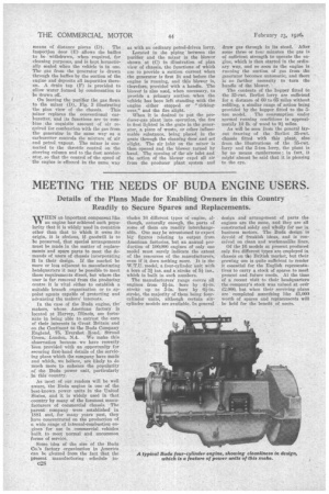
On leaving the purifier the gas flows to the mixer (1)), Fig. 3 illustrating the plan view of the chassis. This .1-iixer replaces the conventional earburetter, and Its functions are to camblue the requisite amount of air required for combustion with the gas from the generator in the same way as a carburetter controls the mixture of air and petrol vapour. The mixer is connected to the throttle control on the steering column and to the foot accelerator, so that the control of the speed of the engine is effected in the same way as with an ordinary petrol-driven lorry.
Located in the pipingbetween the purifier and the mixer is the blower shown at (C) in illustration of plan view of chassis, the functions of which are to provide a suction current when the generator is first lit and before the engine is running, and this blower is, therefore, provided with a handle. The blower is also used, when necessary, to provide a primary suctionwhen the vehicle has been left standing with the engine either stopped or "tickingover," and the fire alight.
When it is desired to put the producer-gas plant into operation, the fire is first lighted in the grate in the generator, a piece of waste, or other inflammable substance, being placed in the grate through the cleaning door and set alight. The air inlet on the mixer is then opened and the blower turned by hand. The opening of the air inlet and the action of the blower expel all air from the producer plant system and
draw gas through in its stead. After some three or four minutes the gas is of sufficient strength to operate the engine, which is then started in the ordinary way, and SO soon as the engine is.., running the suction of gas from the generator becomes automatic, and there is no further necessity to turn the handle of the blower.
The contents of the hopper fitted to the 35-cwt. Berliet lorry are sufficient for a distance of 60 to 65 miles without. refilling, a similar range of action being provided by the hopper fitted to the 5ton model. The consumption under normal running conditions is approximately 10 lb. of wood to 9-i miles.
As will be seen from the general layout drawing of the •Berliet 35-cwt. chassis fitted with this plant, alsofrom the illustrations of the 35-cwt. lorry and the 5-ton lorry, the plant is by no means cumbersome ; in fact, it . might almost be said that it is pleasingto the eye.