


Worm.driven Axles for Commercial Vehicles.
Page 3
Page 4
Page 5
Page 6
If you've noticed an error in this article please click here to report it so we can fix it.
Among the many hotly-debarpd points relating to the construction of motor vehicles, none has been more strenuously contested than the design of rent axles. The combatants have been roughly divided into two camps: "solid axelites " and "live axelites," the "solid " party being sub-divided into "chair drivers" and " rack and pinionists," whilst the live" party consists of " worms" and '' bevel drivers." The merits of each type of drive and the answer to the question of " which is the best " for commercial vehicles, are not subjects that can be tcduced to formulie, because 80 much depends upon the conditions of service for which a chassis is intended when taken over.
We discussed various aspects of this question in an article on the " Final Drive for Commercial Vehicles," in our issues of the 14th and -21st March, 1907. It will generally be admitted that, provided the vehicles are operated over " made " roads, and the
wheels are fitted with solid-rubber tires, " " axles in many instances are suitable for the following two classes of machines : .
(1) Passenger-carrying vehicles, either for publicservice or private hire ; (2) Goods vehicles up to four tons capacity. Solid axles will generally be found more suitable for vehicles of the following classes :— (3) Freight vehicles for loads exceeding four tons ; (4) Colonial types which demand good ground clearance ; (5) Vehicles with steel-tired wheels.
We do not intend, in the course of this article, to deal with vehicles in classes 3, 4, and 5, and, se far as concerns classes 1 and 2, it is our present purpose to discuss only that type of " live" axle in which a worm and worm-wheel are employed, as is now in use on a large number of London motorbuses. The development of the worm-drive for such vehicles has been the natural outcome of the high standard of silence which was set by the licensing authorities at Scotland Yard. This type of drive can be made more efficient, and it will tun more quietly than bevel gearing or any other form of drive, provided, of course, that the worm and worm-wheel are correctly designed, accurately cut, and carefully fitted.
In the course of such a short article as the present one, it would not be possible to deal with the technical questions of worm contact and tooth-design. In most cases, manufacturers will find ii better to obtain cutters from first-class tool-makers, and not to attempt to produce such cutters in the tool-rooms at their own factories.
The design of a worm and worm-wheel should be governed by many opposing factors, and, to a great extent, it resolves into a question of "give and take." The controlling points, however, may be summarized as follow:(a) Available space ; (b) efficiency ; and (c) facility for taking up end-thrust. Availabie Space.
Tie, available space a ill be determined by the required ground clearance and the diameter of the roadwheels to be employed. The average requirements of,a three-ton vehicle demand that it shall have tires with a maximum diameter of about 10 in., thus giving a distance of 20 in. from the centre of the wormwheel to the ground.
If allowance is to be made for a clearance of 12 in. when the tires are new, a distance of 8 in. is then left for the outside radius of the axle casing, and, if the casing is constructed in the form suggested later, the available space left for the worm-wheel allows for its having a maximum overall diameter of 131 in.
Efficiency.
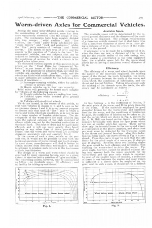
The efficiency of a worm and wheel depends upon the nature of the materials employed, the rubbing speed of the thread, the tooth formation, the intensity of pressure between the teeth of the worm and worm-wheel, the conditions of lubrication, and the thrust and journal friction. Taking into account only the rubbing of the threads upon the teeth, the efficiency may be calculated as follows :—
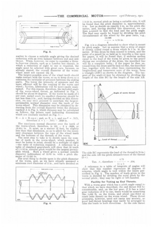
In this formula /4 is the, coefficient of friction, P the axial pitch of the worm, and D the pitch diameter of the worm. If the materials employed be good phosphor bronze for the worm-wheel and hardened steel for the worm, and the conditions of lubrication be good, the coefficient of friction my be taken as .05, and the curves which are shown in Fig. 1, plotted by Mr. C. W. Hill, are based on that figure ; the results compare favourably with those for spur gears which are run at similar pitch-line speeds. These curves show only the internal losses in the worm and wheel, as represented in the above equation, and about four per cent, must be deducted for the frictional losses in the thrust and journal bearings ; after this deduction has been made, the curve shown in Fig. 2 is produced. From this curve it may be seen that the safe limits for the Ditch angle of a worm are 20 degrees and 45 degrees: Between these two limiting angles the gear would be both efficient and reversible, thus enabling the worm-wheel to drive the worm. The pitch angle, however, cannot be decided without taking into account both the space available for the worm-wheel and the gear ratio which is required. in most of the smaller types of vehicles, a reduction of three to one between the engine and road wheels is sufficient if a direct drive be employed on top gear, and, in such a case, it should not be a difficult matter to choose a suitable angle giving the desired reduction with an even balance between end and side thrust. When, however, we come to consider a threeto-four-ton chassis, such as a London bus chassis, in which a reduction of eight to one is required, the angle must be selected with great care, because, as already stated, the overall diameter of the wormwheel must not exceed 13i in.
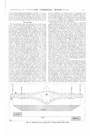
The largest-possible area of the wheel teeth should make contact with the worm, so as to keep down to a minimum the intensity of pressure between the sliding parts. The lower the intensity of pressure and the more efficient will be the running of the worm and wheel ; further, lubrication will be more-easily maintained. For this reason, therefore, the included angle of the worm-wheel throat, as indicated in Fig. 3, should be about 90 degrees. If the worm be made of 3 per cent, nickel steel, its smallest diameter should be not less than 2 in., and, having decided on this dimension, we may next proceed to ascertain the largestpermissible normal diameter over the teeth of the worm-wheeI. This dimension may be obtained by deducting from the overall diameter twice the distance marked A in Fig. 3, which distance may be calculated as follows, the letters used indicating dimensions which are similarly marked on Fig.
— A = R cos s ; and, as R 1, and ces 8 =.7071,
therefore A = 1 — .7071 = .2929 in.
The maximum normal diameter over the teeth of the worm-wheel, therefore, is 13i— 2 x .2999, or 12.914 in. It must, as a matter of fact, be slightly less than that dimension, so as to allow for the necessary clearance between the tops of the wheel teeth and the bottoms of the threads of the worm.
The next step to take is to decide upon the number of teeth in the worm-wheel, which number, it must be borne in mind, should be a multiple of eight —the ratio of reduction required. A reference to a table of standard gearwheels will show that 32 teeth of 1 3-16 in. circular pitch would be the largest-permissible wheel.. Such a wheel gives a normal outside diameter (addendum) of 12.85 in. with a pitch diameter of 12.095 in.
The next thing to decide upon is the pitch diameter of the worm, and, as we have already assumed a minimum root diameter of 2 in., and have decided on 1 3-16 in. normal pitch as being a suitable size, it will be found that the pitch diameter is, approximately, 3 in. Let us decide on exactly 3 in. as the pitch diameter, and, having decided this dimension, we can then psoceed to find the lead and the pitch angle. The lead may easily be found by dividing the pitch circumference of the wheel by the gear ratio, e.g., 12.095 = 4.75 in.
8 Fig. 4 is a diagram intended to show what is meant by pitch angle. Let us assume that a strip of paper is closely coiled round a drum which Is 3 in. in diameter. If this drum be then caused to rotate, and the point of a pencil be so held as to inscribe a line upon the paper, it will be found that, if endwise motion equal to the lead of the worm be given to the pencil during one revolution of the drum, the inscribed line will be a complete helix ; if the paper be then unwound from the drum and be laid out flat, the inscribed line, together with two other lines representing the longitudinal and transverse axes of the worm, form a triangle (ABC) as shown in the diagram. The tangent of the angle (i) may be obtained by dividing the length of the side BC by the length of the side AR and the side AB the pitch circumference of the thread The side BC represents the lead of the thread (4.75 in.) (3 4.75 Tan. therefore = = .504.
11 x
A reference to a table of tangents of angles will show that this number represents 26 degrees 45 minutes, which angle is well within the limits prescribed in Fig. 2. The number of leads given to the worm is decided by dividing the axial pitch by the normal pitch ; they may be right or left-handed.
Facility for Taking up End Thrusts.
With a worm gear which has a pitch angle equal to that which we have described, the end thrust will Jar considerable, and, on the low gear, if it has a total gear reduction of 27 to one, there would be something like 3,000 lb on the worm, and about one-third as much (side thrust) on the worm wheel. These thrust pressures, however, need not cause any anxiety, as good ball-thrust bearings may easily be arranged to take the loads in both directions. As the side thrust
on the worm-wheel is frequently reversed, the wormwheel flange should be placed between the two halves of the differential-gear casing, and should not be bolted on to one side in the manner of a bevel wheel, as, if the wheel were fitted in the latter manner, the bolts would be placed in tension as well as in shear,
The Casing.
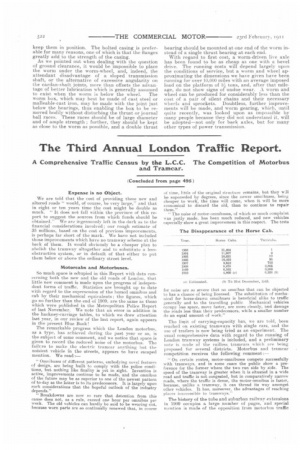
Having decided upon the general form and dimenshms of the worm and worm-wheel, a not-less-difficult problem is now presented : that of providing them with a casing which will keep the alignment of the parts and maintain the pitch centres at their proper distance. It should also have suitable recesses for thrust and journal bearings, should be strong enough to support the load and to take both the torque and driving effort, should be light, and, last but not least, it must be a commercial proposition from the manufacturing point of view. Until quite recently, live-axle cases were usually built up of two trumpetshaped castings, which were bolted together with the flanged joint on the longitudinal centre line of the chassis. Spring brackets were sometimes east integral with these casings, but more often the spring brackets were carried on steel tubes which were pressed into the trumpet-shaped casings. This type o axle suffers from two inherent defects : one is that the cast metal casing cannot conveniently be made of suitable shape to withstand heavy stresses either in tension or in shear ; the other is that fatigue is very soon manifest, owing to the rapid vibration to which an axle is subjected, and, consequently, Fracture sooner or later occurs near a change of section in the casing. These difficulties undoubtedly retarded the adoption of live axles for heavy commercial vehicles far more than did the minor troubles of noisy bevels and rapidly-wearing worm gears, and the then-tried remedies of increased thickness of the metal casing (involving greater unsprung weight upon the tires) and the provision of tie rods (which generally worked loose) were worse than the evils they were intended to cure. As in many other instances, improvements in other branches of engineering brought help to the harassed motor-vehicle designer, and the advent of high-temperature welding methods, together with improvements in heavy presses, were quickly appreciated by light-car builders who at once proceeded to manufacture pressed-steel axle cases. For heavy commercial vehicles, the pressing of these casings pie sented increased difficulties, chiefly owing to the greater thickness of metal which is required, but, now, at least one type of vehicle is running which has a mild-steel live-axle casing with which is incorporated spring brackets, yet which does not necessitate the use of a single bolt in tension or that tie rods, to the use of which most engineers take exception, should form any part. of its structure.
The shape of the case may be made to suit individual requirements, but the form which is shown in Fig. 6 has been found very successful on a three-tofour-ton lorry which has been tried over some of the worst roads in England and America. if we neglect the weight due to the worm and differential, the bending and shear stresses, due to the weight of the vehicle and its load, will be shown in the diagrams below the view of the axle casing. From these diagrams it will be seen that the greatest strength is needed between the spring centres, and provision for this may be made by increasing the diameter of the casing towards the centre. The weakest points are where the axle enters the road wheels, as, here, the diameter must be reduced, in order that the hubs may be of reasonable size, yet this occurs at positions in which the shear stress is considerable. Increased strength will be obtained if the flanges (D) are eontinued right through to the ends of the casing ; sleeves may then be pushed over the ends of the. casing, in order to provide journals on which the wheels may run these sleeves being held in position laterally by stop pins (E). This method of construction facilitates the machining of the parts, and they are also easily renewable. If ball or roller bearings are employed, they may be fixed direct on to the casing, and sleeves would not then be necessary.
The bearing housings for the inner ends of the differential shafts may be made as mild-steel stampings (G), which stampings may either be welded or riveted to the main easing. Theoretically, the thickness ssf the complete main casing may be less in the centre than at the ends, on account of the increased diameter towards the middle, but the reduction in weight effected by such thinning of the metal hardly justifies the expense of having the plates rolled after cutting them to shape. In the process of stamping, however, the thickness of the material will be reduced in the centre by from El to 15 per cent. The two halves of the casing may be welded together instead of being flanged and bolted as shown. This necessitates that the driving shafts shall be pushed through from each end, and some fixing must be provided in order to keep them in position. The bolted casing is preferable for many reasons, one of which is that the flanges greatly add to the strength of the casing. As we pointed out when dealing with the question of ground clearance, it would be impossible to place the worm under the worm-wheel, and, indeed, the attendant disadvantage of a sloped transmission shaft, or the alternative of excessive angularity on the cardan-shalt joints, more than offsets the advantage of better lubrication which is generally assumed to exist when the worm is below the wheel. The worm box, which may best be made of east steel or malleable-cast iron, may be made with the joint just below the bearings, thus enabling the box to be removed bodily without disturbing the thrust or journal ball races. These races should be of large diameter and of ample strength ; further, they should be kept as close to the worm as possible, and a double thrust bearing should be mounted at one end of the worm instead of a single thrust bearing at each end.
With regard to first cost, a worm-driven live axle has been found to be as cheap as one with a bevel drive. The running costs will depend largely upon the conditions of service, but a worm and wheel approximating the dimensions we have given have been running for over 10,000 miles with an average imposed load on the platform of 31 tons, and, after that mile
age, do not show signs of undue wear. worm and wheel can be produced for considerably less than the cost of a pair of silent chains and their necessary wheels and sprockets. Doubtless, further improvements will be made, and worm gearing, which, until quite recently, was looked upon as impossible by many people because they did not understand it, will be adopted—not only for baek axles, but for many other types of power transmission.