a moving vehicle by converting the kinetic energy which the
Page 27

If you've noticed an error in this article please click here to report it so we can fix it.
vehicle posses i heat. This is accomplished in various ways, but before going into details of the various types of brakes, the main requirements of a braking system must be considered: brakes must be capable )ing the vehicle to rest in urtest possible distance in emergency arises.
?re must be variable con: one end of the scale it )e possible to bring the to rest smo4thly when a routine stop, while at ler the vehicle must be le of making an emerstop with the maximum retardation. In between two extremes must be f retardation to fit every stance.
lere must be ease of on. There is a limit to the lar effort a driver can then applying the brake, n it is necessary to supp his push on the brake )y some other means, eg nce by compressed air or le brakes must be fully nsating, ie there must be Jal braking force at the of each axle. If this is not ;e the vehicle will tend to one side when the brakes plied, particularly if the 1 braking occurs on the ; of the front axle.
lere must be complete ity — there is no need to ut the dire consequences may result from brake kes must have a long life e easy to maintain and lere must be provision in the system to hold the ) stationary when it is uned.
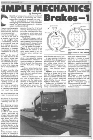
dern braking systems eveloped from the simple il expanding shoe system in Figure 1.
e, it will be seen, are two shoes, anchored by of a pin to the brake back The shoes are forced apart cam when the driver 3 the brake. Each shoe is section and is lined with :eable friction material, riveted or bonded to the The shoes are pulled off ring when the brakes are
?,d.
brake drums are made of an, which as a material is iuitable for use with an
asbestos lining,-Tas it is hard wearing, cheap and easy to produce, able to withstand the high temperatures which occur, and less likely to distort than some other materials.
The brake linings are made of an asbestos-based material with resin to assist the bonding and sometimes with pieces of metal to help in dissipating the heat.
In the brake illustrated in Figure 1, the cam end of one shoe meets the rotation of the drum, which tends to pick up the brake shoe, pulling it on harder.
This self-applying action gives a more powerful braking force on this shoe. The action of the drum rotation on the second shoe is to pull the shoe away from the drum, thus limiting its effect.
A brake shoe having this self-applying action is called the leading shoe, while the one which the drum repels is known as the trailing shoe.
When a vehicle fitted with this type of brake layout is reversed, and the brake drum revolved in the opposite direction, what was formally the leading shoe becomes the trailing shoe and the trailing shoe becomes the leading one.
In many vehicles, in order to make both shoes do equal work and to provide a servo action, the brake shoe layout is modified so that both shoes become "leading", hence the term "two leading shoe" brakes.
Figure 2 is an illustration of this type of brake and in this case the leading edge of each' shoe is pushed towards the drum by a piston operated hydraulically .(more about hydraulic brakes later).
Brakes may be operated by any one of the followin_g means, or by a combination of two or
more of the methods listed: (a) Cable — limited to motor cycles and for handbrakes on some of the smaller vehicles.
(b) Rods — used for handbrakes on some smaller vehicles and in connection with the systems described in (c), (d) and (e).
(c) Hydraulic — now almost universal on private motor cars and light commercials, (d) Vacuum — used to supplement the driver's effort in applying the brakes in the previously described systems.
(e) Air — the system used on heavy commercial vehicles.
In the next article I will look at hydraulic brakes.


