


An Er
Page 46
Page 47
Page 48
Page 49
If you've noticed an error in this article please click here to report it so we can fix it.
eIy New
GUY 10-1 :-TONNER
IT is not surprising, in the light of recent events in the road-transport industry, that larger and larger goods vehicles should be produced to cope with the ever increasing field of operations which the economic conditions of road . haulage produce. Nowadays a manufacturer or importer can invariably distribute his wares over a tremendously wide area of the country, from a manufacturing town or a port, at a lower cost than when using the railways and, which is often more important, very much more quickly; furthermore, a road journey is from door to door—a great consideration when heavy packages have to be handled.
. The latest addition to the ranks of "heavies" is a Guy 10-12-ton sixwheeled vehicle which, shod with giant pneumatics, is capable of conveying its rated load conveniently and " comfortably" over main highways and secondary roads at relatively high speeds. It is powered by a six-cylindered engine with a good power output and, as such items as steering, springing and bmking have received. the careful attention of the producer, the machine is easily handled despite its size, and fragile goods can be carried (providing they, be reasonably well packed) without fear of breakages B32 occurring by reason of vibration and road shocks.
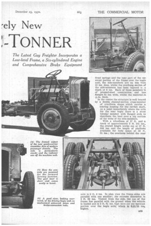
The frame is really substantial, and is built in more or less orthodox manner of channel-sectioned sidemembers suitably braced transversely. As will be seen from the illustrations, the frame members themselves have been graduated in depth to suit the conditions of load, thus at the point between the rear support of the
front springs and the rear part of the upswept portion of the frame over the bogie axle, the side-members are no less than 12 ins, deep, whilst the overhung section. of the side-members has been tapered tc a depth of 8 ins. Each of these members-is of pressed-steel construction and has flanges 3i ins. wide, whilst the material,is
thick.
In the centre the structure is well braced by a double channel-section cross-member of cruciform shape which carries a bearing housing for the cardan shaft. At a point immediately above the axle for the rear bogie there is a stout tubular member with flanged ends to distribute the load over a big nortion of the webs of the side-members.
With a wheelbase of 17 ft. and a track of approximately 5 ft. 10.1 ins., the overall length works out at 27 ft. -101 ins, and the length of platfortu available for body space at 22 ft. 21 ins.; the overhang behind the rear
axle is 8 ft. 4 ins. In plan view the frame sides are parallel with one another; the extreme diniensionis 2 ft. 91 ins. Viewed from the side, the top of the frame lies parallel with the ground when the vehicle is loaded and is 2 ft. 81ins, high save tor. cne Upswept portion over the bogie axle.,: which ia 8,11/16 ins, higher.
As might be expected, the well-tried six-cylindered Guy engine is employed. With bore and stroke dimensions of 4i ins. and 54 ins, respectively, the unit has a total piston-swept volume of slightly more than 468 cubic ins. (7,688.6 c.c.) and develops 105 b.h.p.; it is rated at 43.5 h.p.
Robustness characterizes the whole construction of the engine. The crankshaft, for example, is of exceedingly sturdy design, with main journals of 21-in. diameter and crank-pins of 2i-in. diameter. Machined all over and carefully balanced, this component is heat treated and should therefore be capable of dealing with the heavy work which a 12-ton load naturally The crankcase is a heavily webbed, deep-sectioned aluminium casting, the bottom half of which is readily detachable for the inspection of the crankshaft main journals and the big-end bearings of the connecting rods. As a further aid to rigidity, the cylinder block is formed in a single casting, the attachment bolts (between the crankcase and the block) being sufficiently large in diameter and sufficiently numerous to prevent relative movement taking place.
Most operators are quite familiar with the design of the Guy patented valve gear, but for the benefit of those who are not an fait with its construction we will• briefly describe it. The valves are steeply inclined to the vertical centre line of the cylinder block, in which the pockets for both inlet and exhaust systems are formed.
Long rockers of light section (to keep down .inertia stresses) connect with a• camshaft housed in the crankcase, the :whole mechanism being entirely enclosed by two aluminium covers, each of which is readily detachable for rocker-valve clearance adjustment.
The cylinder heads, of whichthere are two, each covering three
cylinders, have perfectly f at under faces and so are very easy to clean when decarbonizing becomes necessary. It might be mentioned that the camshaft is case hardened and runs on eight bearings, each of which consists of a substantial phosphor-bronze bush ; there is an adjustment for endwise location. Aluminium pistons are used.
Submerged in a SUMp of four gallons capacity is a gear-type pump driven by a vertical -spindle from the camshaft. It is surrounded by a gauze filter and delivers oil under pressure to a cast-in gallery whence the main journals of the crankshaft ttre fed with a B$4
copious supply of lubricant; the big-end bearings of the connecting rods, of course, obtain their oil through drilled passages in the crankshaft itself.
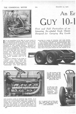
The auxiliary drive consists entirely of helical gears, the layout of the timing case being so arranged that all units requiring attention' are Mounted on the near side of tile engine. On the near side and off side respectively of a cross-shaft running at the top of the timing case are the water pump and magneto; both these components are accessible owing to the fact that thcaf are situated high in relation to the engine. A fan driven
by an endless V-belt from the crankshaft operates in a cowl fitted to the rear face of the radiator, in such a manner that maximum efficiency for the air stream is assured.
A new clutch is employed in which the friction surfaces have been increased so that this hard-worked component is even more " on top of its work" than in the past. Three multiplying levers, easily adjustable, ensure a light pedal pressure, whilst an adjustable clutch stop fitted on the front end of the gearbox assists the driver in making rapid upward changes.
As is usual in vehicles designed for exceptionally heavy loads this six-wheeled Guy machine has an auxiliary gearbox in addition to the normal Guy four-speed type which has been used during the past few years on many passenger and goods vehicles. The operating levers are, of course, separate. The main four-speed box has the following ratios-9.66, 16.71, 35.1 and 48.25 to 1. When these ratios are compounded with the auxiliary reduction the overall ratios become 32.62, 56.8, 118.2, and 163.2 to 1. The propeller shaft is divided into two short lengths, each equipped with a large cross-pin universal joint.
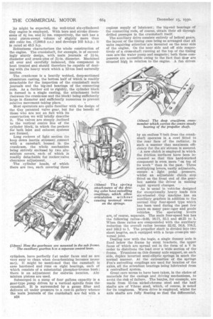
Dealing now with the bogie, a single dummy axle is fixed below the frame by stout brackets, the upper faces of which are spread out in the form of a V in order to distribute the load over a wide section of the frame. Trunnions on this dummy axle support, on each side, duplex inverted semi-elliptic springs in much the normal manner. At the extremities of the springs Fox's swivelling couplings are used for location of the axles, all the attendant bearings being lubricated from a centralized system.
Great care seems to have been taken, in the choice of materials for the casings and driving mechanisms, to avoid the risk of failure. The banjos, for example, are made from 55-ton nickel-chrome steel and the half shafts are of Vibrac steel, which, of course, is noted for its toughness. Worm drive is employed, -whilst the axle shafts are fully floating so that the differential, worm wheels and half-shafts can be removed without the aid of a jack and even without removing the road wheels.
Special precautions have had to be taken in the design of the braking system in order that the vehicle shall be thoroughly under control when serving under arduous conditions of load in hilly districts. All the wheels are braked. The bogie axles are each equipped with drums of 20 ins, diameter and the shoes are no less than 5 ins, wide; on the front wheels, drums of 18i ins, diameter and shoes 2.3/16 ins, wide are fitted. The hook-up is rather interesting.
Two Dewandre vacuum cylinders are employed, one on each side of the frame. The pedal operates these two components and by a simple linkage the frontwheel brakes and the brakes on the leading axle of the bogie are applied ; the hand lever acts only upon' the trailing axle of the bogie.
The specification is completed by a 50-gallon cylindrical fuel tank which is fitted to the near side of the frame by substantial pressed-steel brackets. Combined main and reserve taps are situated near a large quickoperating filler cap. The driving position is alongside the engine to give additional body space; a Marles reduction gear is used.
Altogether we may confidently give the opinion that this is a fine vehicle and one which should stand up to prolonged hard work.