


CLEANSING OIL BY CENTRIFUGAL SEPARATION.
Page 32
If you've noticed an error in this article please click here to report it so we can fix it.
A Résumé of Recently Published Patent Specifications.
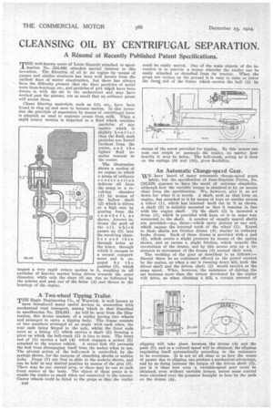
TrIE■ well-known name of Louis Renault attached to specification No. 224,492 attaches special interest to this invention. The filtration of oil in an engine by means of gauzes and similar strainers has been well known from the earliest days of motor construction, but there has always been the difficulty present that the finer particles of metal worn from bearings, etc., and particles of grit which have been drawn in with the air to the carburetter and may have worked past the pistons, are so small that no ordinary gauze will arrest them.
Closer filtering materials, such as felt, etc., have been found to clog up. and soon to become useless. In this invention the principle of separation by means of centrifugal force is adopted, as used to separate cream from milk. When a rapid rotary motion is imparted to a fluid which contains particles of any matter which is slightly he avier than the fluid, such particles are forced farthest from the centre, and the lighter fluid remains nearest to the centre.
The illustration shows a section of an engine in which a pump of ordinary constr uction delivers oil from the sump to a revolving chamber (1) by means of the hollow shaft (2) which is driven at a high rate by gearing from the -camshaft, as shown. Arrows indicate the path of the oil. which passes up (2) into the revolving chainbe r and then through holes at the lower, through which it escapes to a second compartment and is engaged by the paddles (3), which impart a very rapid rotary motion to it, resulting in all particles of heavier matter being driven towards the outer diameter, while only the clean oil can rise as indicated by the arrows and pass out of the holes (4) and thence to the bearings of the engine.
A Two-wheel Tipping Trailer.
THE Eagle Engineering Co., of Warwick, is well known to
have introduced many useful devices in connection with mechanical road transport, among -which is that described in specification No. 224,641. As will be seen from the illustration, this device consists of a trailer having two wheels and arranged to carry a tipping body. The frame consists of two members arranged at an angle with each other, the rear ends being hinged to the axle, whilst the front ends meet at a fitting (1) which carries a shaft (2) forming a pivot on which the bell-crank (3) is free to turn. The front end of (3) carries a ball (4) which engages a socket (5) attached to the tractor vehicle. A cotter bolt (6) prevents the ball from disengaging itself from the socket when in use. The pivotal action of the bell-crank is controlled, by the springs shown, for the purpose of absorbing shocks or sudden jerks. Props (7) are free to slide in the sockets shown, and can be held in any desired position by means of the pins (8). There may be one central prop, or there may be one at each ;vont corner of the body. The object of these props is to enable the trailer to stand when not connected to the tractor. Castor wheels could be fitted to the props so that the trailer
B48 could be easily moved. One of the main objects of the invention is to provide a means whereby the trailer can be easily attached or detached from its tractor. When the props are resting on the ground it is easy to raise or lower the frog end of the frame which carries the ball (4) by
An Automatic Change-speed Gear.
WE have heard of many automatic change-speed gears
lately, but the specification of Jean-Baptiste Perrin, No. 216,529, appears to have the merit of extreme simplicity, although how the variable torque is obtained is by no means clear from the specification. We, however, give it as set down. for what it is worth. A shaft, such as that from an engine, has attached to it by means of keys or similar means a wheel (1), which has internal teeth cut in it as shown. A shaft (2) is suitably mounted so that it remains in line with the engine shaft. On the shaft (2) is mounted a drum (3), which is provided with keys, or is in some way connected to the shaft. A number of equally spaced shafts are provided—say, three—which carry pinions at one end, which engage the internal teeth of the -wheel (1). Keyed to theSe shafts are friction drums (4), similar to ordinary brake drums. Each of these drums is provided with a pad (5), which exerts a slight pressure by means of the spring shown, and so causes a slight friction, which retards the revolutions of the drums, and by this means sets up a resistance to movement of the drums (4) around their axes.
The working of the gear as described is as follows:— Should there be no resistance offered to the power exerted by the engine, as when a car is running down hill, both the driver shaft and the driven shaft (2) would revolve at the same speed. When, however, the resistance of driving the ear becomes more than the torque developed by the engine will drive, as when climbing a bill, a certain amount of means of the screw provided for tipping. By this means one ntan can couple or uncouple the trailer, no matter how heavily it may be laden. The bell-crank, acting as it does on the springs (9) and (10), gives flexibility.
slipping will take place between the drums (4) and the pads (5), and so a reduced speed will be obtained, the slipping regulating itself automatically according to the resistance to be overcome. It is not at all clear to us how the waste of power due to slipping can produce a mechanical advantage, and by so doing increase the torque of the driven shaft (2), nor is it clear how even a variable-speed gear could be obtained, even without variable torque, unless some control were exercised over the pressure brought to bear by the pads on the drums (4),