


SOME ENGINE POINTERS.
Page 31
If you've noticed an error in this article please click here to report it so we can fix it.
Interesting Contributions from Our Driver and Mechanic Readers.
SIMPLE as the modern engine may appear to be to the uninitiated, there are actually many points about it which require expert knowledge if its high efficiency is to be maintained, and it is for this reason that this week we devote this page to letters dealing with various details in the upkeep of petrol engines.
The best letter (to which we award the special prize of 15s.), so far as the value and novelty of its contents are concerned, is from " A.W.R.," of Canterbury. Some little time ago he was asked to cure a fault in a petrol engine of which the little-end bushes were not getting sufficient oil, and, consequently, had to be re stewed at frequent intervals ; excessive wear also took place on the gudgeon pins, which, in themselves, were fairly expensive, quite apart from the loss of time occasioned by the necessity for taking down the engine.
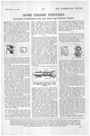
In order to cure the complaint, a length of thin brass tube, an easy fit within the centre boles of the gudgeon pins (which were luckily hollow), was cut into lengths of 3 ins. One end of each length was cut on the bevel, and a brass disc soldered into it. The top of the tube immediately above the disc was then cut away in the manner shown in the illustration, so that the tip formed a kind of scoop.
There were several holes in each gudgeon pin for the purpose of lubrication, and similar holes were set out and drilled in the tubes. At the bottom of each tube was cut a slot to take the end of the gudgeon pin screw, by which it could be prevented from turning and yet be free to slide. In order to hold the scoop end of each tube against the cylindet wall, a light spring was fitted at the other end of the tube, and a brass disc driven into the end of the gudgeon pin to hold the spring up to its work. The result of fitting this device is that, as each piston rises in its cylinder the scooped tube is pushed lightly against the wall and scoops the oil into the tube and thence through the holes into the smallend bearing, effectually lubricating it.
A considerable amount of work has been done by the engine fitted with this device, and no sign of wear has since occurred in the bushes.
A VERY useful tip in connection with valves has been sent to us by
• "2 G.B.," of Penarth. He had, he tells us, a very considerable amount of trouble with burning and sticking valves. . He surmounted it by fitting each stem
with a washer of felt an inch thick, and recommends this course as a regular thing. The washer should be made a sliding fit on the valve, and a tight fit inside the spring. It must be soaked in hot engine oil for about half-an-hour before being fitted. Valves equipped with these washers can easily be removed and have clean, well-lubricated stems which slip through the valve guide with ease. r
IN many vehicles considerable trouble is experienced through constant leakage from the glands of the water pump. On examination, says " H.C.H.'," of Sheffield, in nine cases out of ten, the difficulty appears to be due to improper packing.
The method adopted by many drivers seems to be to take a length of packing and to wrap this around the spindle in the opposite direction to its rotation, and then to tighten up the gland nut or screws until the water ceases to drip. This method is entirely wrong, and proves satisfactory only for a day or so.
The object of constructing the gland with coned ends is to allow the packing to contract on to the spindle when pressure is applied ; but if the packing be merely wound round, it only contracts in the one direction, i.e., along the line of pressure, and exerts barely any grip on the spindle.
To pack the joints correctly, obtain suitable material, usually called tallow packing, which can be obtained at any millwrights' stores, and should be of a diameter sufficient to permit it to be pushed between the gland and the spindle without undue exertion. Measure the diameter of the spindle, cut off a piece of packing three times this diameter, and on placing it round the spindle it will he found that the edges butt together.
Now rota little piece more off the packing to allow a clearance of approximately
in. between the ends, and push it into the gland, using a piece of wood, not metal, as this may score the surface of the spindle. Cut a second piece in the same way, and insert this so that the space between the ends is opposite that in the first ring. Proceed in a similar way with the third, and, if necessary, a fourth piece, until the gland is full. Now it will be found that the slightest pressure on the gland nut will cause the packing to be
forced against the coned faces, and as the rings are split they will push in against the spindle, if the packing obtained proves to be slightly too large for the gland, it should not be hammered, as this will destroy the fibre ; instead, it • should be placed between two pieces of board and squeezed.
ENGINE timing forms the subject of the letter from "Mil.," of Trowbridge. Often; he says, it is necessary to rethne the magneto on the engine, but a few hints may be acceptable to those who do not quite understand the procedure. Assuming that everything has been dig arranged, it is as well to determine the order of firing of the different cylinders.
This is done by watching all the inlet or all the exhaust valves, and turning the engine slowly, care being taken to notice which ones open and close after the others, commencing with the cylinder nearest the radiator, which is usually called No. 1. Most English four-cylinder engines fire 1, 3, 4, 2; some American and Ford vehicles 1, 2;4, 3; and six-cylinder engines usually 1, 5, 3, 6, 2, 4.
The next step is to ascertain when the piston is at the top of the first stroke in No. 1 cylinder. This can usually be done by removing a sparking plug, compression tap or valve tap, and inserting a piece of wire so that the extreme lift of this wire can be noted. Sometimes the flywheel is marked ; in other cases the piston can actually be seen.
When the piston has reached the top dead centre in No. 1 cylinder, the exhaust valve has just closed, and the inlet is be ginning to open in No. 4 cylinder. By gently rocking the flywheel backwards and forwards and watching these two valves closely, another indication is obtained as to the position of the piston.
Now, as regards the magneto : first remove the contact-breaker cover and the high-tension distributor, turn the mag neto armature in the running direction and -stop it when the points are just breaking when in the retarded position,
and while the distributor brush is opposite the correct sector this should be
coupled to No. 1 cylinder. The next hightension wire will go to the next cylinder in order of firing, note being taken that the distributor moves in the direction opposite to the armature.
If the magneto has fixed ignition, a little more advance will be necessary.