


Engines—(I). The Tylor.
Page 4
Page 5
Page 6
If you've noticed an error in this article please click here to report it so we can fix it.
The First of a Series of Articles Dealing with the Power Units as Employed on Many of the Commercial Vehicles of To-day.
There are many differences in respect of design and construction of commercial vehicles between the practice in this country and that adopted by makers in the United
States of America. In the matter ofdesign these differences are partly due to the class of country iii which the machines are employed, p4tly to the variation in theclass of:.-work with which they have to deal and again to a considerable eident, owing to the fact that the commercial vehicle per _se has seen longer service in this country than it has across the Atlantic.
Manufacture v. Assembly.
In the matter of the construction of the whole vehicle, the outstanding feature of American practice is undoubtedly the method of building up from units bought-from different makers, each of winch, specialize_s in one particular portion of a chassis only. In Great Britain, on the other hand, the reverse is more often than not the rule. The majority of makers in this country are able to state that, to -all intents and purposes, they design and manufacture the complete chassis which they sell and which bear their name.
We are not, on the present occasion. about to devote space to a discussion of the relative merits of these two methods of construction nor is it convenient to discuss the effect which they have on the ultimate selling price of the machine when built. Both of these considerations must be reserved for a later chapter.
There are, of course, exceptions to every rule, and the old tag applies to this matter of vehicle construction to no less an extent than to other things. Until very lately, however, the British exceptions only extended to the .power unit.. B92 British Engines.
It is our present intention to describe in detail some of the most popular units as used in assembled British and American vehicles of to-day. It is only natural in the first place that we should commence with one which is the product of a British manufacturer. The present series will deal with " the engine."
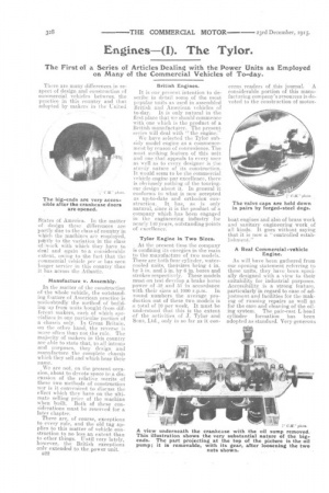
We have selected the Tylor subsidy model engine as a commencement by reason -of convenience. The most striking feature of this unit and one that appeals to every user as well as to every designer is the sturdy nature of its construction. It would seem to be the commercial vehicle engine par excellence, there is -obviously nothing of the touringcar design about it. In general it conforms to what is now accepted as up-to-date and orthodox construction. It has, as is only natural, since it is the product of a company which has been engaged in the engineering industry for nearly 110 years, outstanding points of excellence: Tylor Engine in Two Sizes.
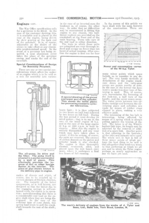
At the present time the company is confining it energies in the'main to the manufacture of two models. These are both four-cylinder, watercooled units, theiysizes being 4 in. by 5 in. and in. by 6 in. bores and strokes respectively. These models must on test develop a brake horse power of •32 and 51 in accordance with their sizes at 1000 r.p.m. In round numbers the average production out of these two models is a total of 10 per week. It must be understood that this is the extent of the activities of J. Tylor and Sons, Ltd., only in so far as it con
cerns readers of this journal. A considerable portion of this manufacturing company's resources is devoted to the construction of motor
boat engines and also -of brass work and sanitary engineering work, of all kinds. It goes-. without saying that it is now a "controlled establishment." .
A Real Commercial -vehicle • Engine.
As will have been gathered from our opening statement referring to these units, they have been specially designed with a view to their suitability for industrial purposes. Accessibility is a strong feature, particularly in regard to ease of adjustment and facilities for the making of running repairs as well as for the care, and cleaning of the oiling system. The pair-east L-head cylinder formation has been adopted as standard. Very generous water spaces are provided. These extend well down the body of the cylinder as well as round the valve chambers. Facing for the exhaust manifold is on the valve side of the.
engine. Tednction passages are cored through the cylinders so as to enable the carburetter to be fitted on to the other and off side, ihue rendering the valves and their tappets much more accessible. The usual quick-detachable covers are provided for the tappets and ti-ear, and adjustment is, of •course, provided for the length of the tappets. The. pistons are of good length and are provided with three lawn cast-iron eccentric rings near the top. The gudgeon pins, which
are casehardened and ground to size are held in place by means of tapered ,set-screws.
Bronze Bearings Lined.
We were struck by the substantial nature of the connecting-rod stampings. These are of H section. The little-ends arc well bushed with phosphor bronze, the big-ends, which by the way are held by four bolts of nickel steel, are fitted with white-metal-lined bearings of gunmetal.
The main bearings are three in number and constructed in a similar manner to those of the big-ends —of gunmetal lined with white metal. A feature of all the engine bearings is the provision of suitable oil grooves, which are cut, partly by machine and partly by .hand, in the surface of the white metal.
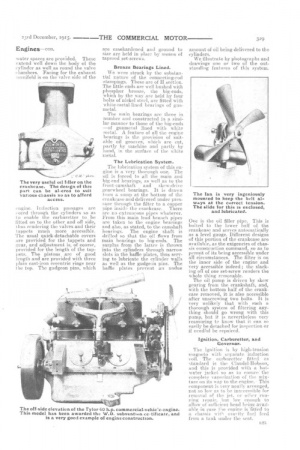
The Lubrication System.
The lubrication system of this engine is a very thorough one. The oil is forced to all the main and big-end bearings, as well as to the front-camshaft and skewdrive gearwheel bearings. It is drawn from a SUMD at the bottom of the, crankcase and delivered under pressure through the filter to a copper pipe inside the crankcase. There are no extraneous pipes whatever. From this main lead branch pipes are taken to the engine bearings and also, as stated, to the camshaft bearings. The engine shaft is drilled so that the oil flows from main bearings to big-ends. The surplus from the latter is thrown into the cylinders through narrow slots in the baffle plates, thus serving to lubricate the cylinder walls as well as the gudgeon pins. The baffle plates prevent an undue
amount of oil being delivered to the cylinders.
We illustrate by photographs and drawings one or two of the outstanding features of this system.
One is the oil filler pipe. This is bolted to the lower half of the crankcase and serves automatically as a level gauge. Different designs of this portion of the crankcase are available, as the exigencies of chassis construction command, so as to permit of its being accessible under all circumstances. The filter is on the inner side of the engine and very accessible indeed ; the slacking off of one set-screw renders the whole thing removable.
The oil pump is driven by skew gearing from the crankshaft., and, with the bottom half of the crankcase removed, it is also accessible after unscrewing two bolts. It is very unlikely that with such a thorough system of filtering anything should go wrong with this pump, but it is nevertheless very reassuring to know that it can so easily be detached for inspection or if needful he repaired.
Ignition, Carburetter, and Governor.
. The ignition is by high-tension • magneto with: separate induction The carburettee fitted as
• standard is the Claudel-Hobson, and this is provided with a hotwater jacket so as to ensure the complete vaporization of the mixture on its way to the engine... This component is very neatly arranged, not so low as to he inaccessible for removal of the jet, or other 'running repair, but low enough-to allow of sufficient head beina.aVailable in case flie engine is.fitted to a chassis with gravity fuel feed from a tank under the seat.
The War Office specification calls for a governor to be fitted. In the case of the customer desiring this, it is available and is placed at the rear of the engine, being driven by skew gearing at the back end of the camshaft. It is, of course, adjustable at the desire of the owner to take effect at any reasonable predetermined speed. In the event of a governor not being required, a neat aluminium cover takes the place of the governor casing, and masks the end of the camshaft.
Special Considerations of Design for Assembly Purposes.
There are one or two special considerations which affect the maker of an engine which is to be sold as a unit for assembly into various The oil-pump, its drive and the filter. The pump itself is situated in a pocket surrounded by a wall of gauze. This el fectually prevents the ingress of dirt or other foreign matter to the interior. The piece of pipe shown broken is the delivery pipe to engine.
makes of chassis and which, of course, has to be coupled up to var3ous designs of friction clutches,
etc. The majority of the latter components, as is well known, are designed so that the thrust due to the engaging springs is 'self-contained while the dutch is in operation; notwithstanding this there is a considerable, end load on the engine shaft when they are being dis
engaged. In the case .of the ordinary type of cone clutch, this spring load tends to pull the crankshaft towards the. rear of the shaft ; n20 in the ease of an inverted cone the tendency is, of course, the other way. In order that no difficulties may be encountered in fitting this engine to any chassis, two ballthrust washers are provided on the crankshaft at the front end of the main bearing. These take care of the end load in either direction.
The tests to which these units are submitted are very thorough indeed and occupy no fewer than ten hours of actual running. After erection the engine is first run for four
hours light ; it is then subjected to two hours on half load followed by two hours on full load. During the last period it mustdevelop its rated power ; that is to say in the ease of the small engine 32 h.p. and in the ease of the large engine 51 h.p. at 1000 r.p.m. hi bath in
stances. After this the engine is entirely dismantled, and any wear which may have taken place is noted ; if this be serious, of course, the parts are renewed. The amount of carbon deposit on the piston and cylinder heads is also checked. The engine is then thoroughly cleaned, re-erected, oiled, and placed upon the test .bench once more, where it undergoes a final two hours of full running. In the course of this article we have dealt with the main features of the construction. There are
many minor points which space forbids us to consider in any detail. The very handy methods of detachment of the engine crankcase doors and the valve-gear covers are points worthy of note. In tile case of the former the locomotive smoke-box-door type of fas tening is used. This, of course, only necessitates the loosening of the lock-nut, a half turn of the handle, and the cover comes away. The water joints between two cylinder castings and between the circulating pipes and cylinders are made by means of rubber rings clipped in place, making a very effective joint.
The tensioning of the fan belt is interesting, being effected by means of a spring which is always pulling against the tension of the belt. The latter is of the Whittle leather-link type, its length may be adjusted by the removal or addition of a spare link. Another point is that referring to the fastening of the inlet and exhaust valve caps. The whole unit in fact is full of these minor points of whiQh rierhaps the best thing to he said is that altogether they tend very much to that perfection at which we all aim and to which the Tylor engine perhaps as nearly approaches as any we have yet seen.