


" Diff. Gears" from U.S.A.
Page 13
Page 14
If you've noticed an error in this article please click here to report it so we can fix it.
Some New Designs of the Self-locking Type from the States.
It has been said elsewhere, of other things, that they make good servants but bad masters. This same trite remark applies with all its significance to the differential gear as used on motor vehicles. It serves, when in circumstances involving different speeds of road wheels it allows of their various velocities, whilst at the same time maintaining the total of their revolutions in direct ratio to that of the propeller shaft. It becomes master on those other occasions when on had roads and with indifferent weather conditions one of a pair of driving wheels fails to grip the road surface and to do its share in propelling the machine. The result, as many of us know to our cost, is that the whole of the engine power is devoted to the task of making this wheel spin, the vehicle meanwhile remaining stationary.
Attempts to Improve the Differential.
There have been attempts almost without number satisfactorily to
solve the problem presented by this latter feature. In heavy tractors, both steam and petrol-propelled, the difficulty has been overcome to a considerable extent by actually locking the differential gear whenever a stretch of road has to be negotiated which is likely to .bring about the conditions as aforesaid. At the best this solution is a clumsy one. The driver is compelled, in order to operate the locking gear, to stop his vehicle and dismount, effecting the locking by actually • connecting the driving mechanism of one wheel to the other by the interpositioning of a pin or pins. In the event of it being possible to lock the gear by means Of a lever or pedal from the driver's seat, it is necessary to include seine form of safely catch to obviate the possibilityof the driver throwing the differential lock in while one wheel of the machine may be spinning round at a high velocity and being therefore possessed of considerable momentum. The probable effect of locking the differential in such cir eumstances would be to strip sonic of the teeth from the gears.
One Example Recently Described.
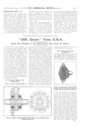
It has been shown, however, that the design and manufacture of a differential gear so constructed as to eliminate this undesirable feature is possible. A short time ago, on the 13th of May to be precise, we devoted some space to a description by Mr. H. Sturmey of the M. and S. type of differential. We may remind our readers that the components or this gear are small worms and wheels, not bevels nor spur gears. The differential starpieee carries two helical pinions or worms with radial axes and also four wheels, of which each one meshes both with one of the radially-disposed pinions and with one of the gears on the axle shafts. The operation of this gear under normal conditions of1road surfaces is as follows :—When coining to a turn, the outer wheel in running ahead of the inner one causes the. helical gears to revolve precisely as is the case with the ordinary type of
differential gear, the pitch angles of the pinions being such that it. is
• possible, if one wheel he locked or prevented from rotating, to revolve its housing by turning the other one. On the other hand, it is impossible to turn the other road wheel by revolving the housing. Consequently, if a wheel should get on to slippery ground, it will not be driven by the engine, the whole of the drive will be transmitted to the wheel which has the grip of the road.
There are also several other differential gears, each designed with the same object in view, and which are at the present. time being offered for sale on the American market. Our illustrations and the groundwork for our text are taken from our contemporary, " The Horseless Age."
Another Similar Gear.
The Walter positive-drive differential is very similar to the M. and S., except that only two pairs of helical pinions are used instead of three.
A Gearless Differential.
In the Gearless differential a different principle altogether is involved. The object which has evi-dently been aimed at in the design of this one is that it must be im31ossible to transmit motion. through its housing to one of the gears alone. Referring to the drawing, the left-hand differential flange (to which the differential driving gear is bolted), the right-hand flange, the centre ring and the right and left driving sector (two at the top and two at the bottom) are all bolted together, making the whole outer differential housing a unit. The right and left ratchets which -ire connected to their respective axle shafts are independent and free to rotate inside of the housing. The two round members with the knobs at the ends and centre, B44
placed crosswise; are the walking beams or pawls, and are the interlocking media between the driving centre and ratchets. The right-hand view shows the right-hand end of the top pawl in the teeth of the right-hand ratchet, and, being driven by the contact piece of the driving sector, this drives the ratchet forward from the centre to the end or the pawl. In the same manner ihe left ratchetis driven forward by the lower pawl which is disconnected at its left end. Thus both wheels are driven forward positively and neither can spin, as with the common differential.
To drive backwards, the differential housing starts to Tnove to the left and pushes the end of the pawl out of the ratchet tooth, which throws the opposite end of the pawl down into the tooth of the opposite ratchet. The contact face of the reverse driving sector engages and drives the wheel backward. The • lower pawl acts in the same manner. In turning a corner, imagine that the car is being driven forward and is to be turned to the. left. The right wheel starts to revolve faster than the left and causes the righthand ratchet, to move faster than the differential housing, which latter can only go as fast as the inner or slower-moving wheel. The ratchet pushes the end of the pawl out of its tooth, thus allowing the ratchet to have a free movement forward. As soon as the corner has been made and both wheels are revolving at equal speed, the spring at the centre of the pawl pushes the end of the pawl back into engagement and the drive is again taken up by both wheels.
When the wheels propel the drive shaft, as in case of coasting or braking through it, both ratchets start to turn faster than the housing, and push the engaged ends of the pawls out of engagement and the opposite ends into the driving position in the opposite ratchet troth, thus causing the ratchets to propel the drive shaft.
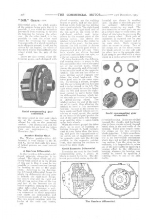
Gould eccentric Differential.
Eccentrics are used in the Gould compensating gear, -a photo. of which is -shown herewith. The different parts which make up the dif ferential are shown in another view. In place of the side gears of the ordinary differential, two double eccentrics are used. The two eccentrics or each pair are set, at a certain angle to each other, the object of this being to overcome the dead centre effect. Each pair of eccentrics is squared out on ono side to receive the square end of the axle shaft. Each eccentric takes an eccentric strap. Two of the straps not on the sameeccentric block extend to one side and. the other two to the opposite side. Each strap is provided with a short shank in a radial groove in the dif ferential housing. Holes are drilled through the shanks, and hardened pins in these shanks extend through radial slots in the end walls of the housing. These pins couple eccentric .straps on the two eccentric blocks together. A little consideration will show that, since an eccentric is an irreversible mechanism which does not permit of transmitting motion from the strap to the eccentric, it is impossible to rotate one of the axle shafts by applying a turning effort to the differential housing, whereas the housing may readily be turned by applying a rotating effort to one of the axle shafts.