


An Improved Pneumatic Governor
Page 66
If you've noticed an error in this article please click here to report it so we can fix it.
PNEUMAT1C governors, as used in injection pumps, suffer from the defect that they respond not only to the general suction, but also to the individual fluctuations of each cylinder. At low speed this can cause uneven running, and a scheme for eliminating it forms the subject of patent No. 778,828. (Etablissements Berry, 92 Rue Bonte Pollee Lille (Nord) France.)
The basic principle of the scheme is to limit the time of connection between intake and governor to the period of maximum piston speed, that is, at about mid-stroke. The value of the suction at that instant corresponds with the greatest possible sensitivity to the variation of engine speed alone.
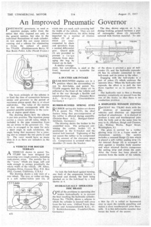
The drawing shows how the scheme is put into practice. The injection pump carries a rotary cut-off valve, which is included in the pipe connection from the air intake to the governor (1). The valve is arranged to be open for only a short angle in each revolution, the angle being that necessary for a rotating slot to connect the two ports (2 and 3). The rotor would have as many slots in it as there are cylinders in the engine: A VEHICLE FOR ROUGH TERRAIN AVEHICLE shown in patent No. 777,889 has been designedfor traversing very rough country, including rock-strewn areas. The novelty lies in the " tyres," which are large, soft and wide enough to .occupy practically the whole width of the vehicle. (W. Albee, Flanders Drive, Canyon Way, P.O. Box 1912, Carmel, California, U.S.A.) The drawing shows a sideview of a rear wheel. The tyre, or rather air-bag, is a soft rubber-fabric unit (1), of
which two are used, each covering half the width of the vehicle. They are not themselves axle-driven, the drive being imparted by a number of friction rollers (2) all of which are interconnected by chain and sprockets from a normal differential gear. Guard skids (3) are provided to prevent a large obstacle from damaging the hag by impact on its hub.
A similar arrange ment, but non-driven, is used at the front, mounted on a turntable for steering.
A DUCTED AIR INTAKE REAR-MOUNTED engines are in a position where the surrounding 'air can be dust-laden, and patent No. 775,638 suggests that the intake air be collected at the front of the vehicle and led to the rear through a flexible and sound-absorbing pipe. (Daimler-Benz
RUBBER-BUSHED SPRING EYES
D UBBER spring-pin bushes are shown
in patent No. 778,521, the chief feature being that pre-compression of the rubber is effected during assembly. (Daimler-Benz A.G., Stuttgart-Untertiirkheim, Germany.) The drawing shows the bushes in the assembled state. The spring-eye containing the rubber bushes (1) is positioned in the U-bracket and the central bolt inserted. Tightening of the nut causes the rubber to be compressed by the amount of the clearance space (2). Compression is arrested when the shoulder (3) meets the bracket.
To lock the bolt-head against turning, one limb of the suspension bracket is upturned and slotted, the limb being pinched on to the bolt-head by a bolt shown at 4.
HYDRAULICALLY OPERATED DISC BRAKE
riNE of the problems in operating disc %--/ brakes hydraulically is to prevent the heat reaching the hydraulic cylinder. Patent No. 778,094, shows a scheme in which the cylinder is located well away from the hot area. (Alfred Tevcs Maschinen und Armaturertfabrik KG., 4153 Rebstockerstrasse, Frankfurt/Main, Germany.) The disc, shown edge-on at I , is, during braking, gripped between a pair of rectangular shoes (2) internally covered with friction material. To one
ot the shoes is pivoted a pair of beltcranks (3), and the hydraulic expander (4) has its cylinder connected to one bell-crank and its piston to the other.
Engaging with the bell-cranks is a pair of yokes (5) which embrace the opposite shbe. ' When the hYdraulic unit expands, the effect is to pull the two shoes together so as to sandwich the disc.
The hydraulic unit is thus a floating member, completely air-spaced from the lest of the brake, so that there is no conduction problerri.
A SIMPLIFIED WINDOW FITTING
1DATENT No. 778,882 deals with the 1. windows of passenger service vehicles and discloses an improved method of attachment. It is claimed to produce a neat and weatherproof joint with the body and at the same time be easy to fit. (Hallam, Sleigh and Cheston, Ltd., Widney " Works, flagot Street. Birmingham, 4.) The glass is carried by a rubber glazing strip (1) in a frame made of aluminium section. The section includes a recessed flange (2) into which is placed a soft rubber sealing strip (3); An internal flange (4) is arranged to abut against a wooden body member and when screwed thereto compresses the sealing strip and closes the joint. After the frame has been placed in position from the inside of the vehicle, a thin lip (5) is rolled or hammered over to meet the outside panelling and makes a close weatherproof joint therewith. It is this deformable member that forms the basis of the patent.