


A New Fuel-injection Pump E-OR some time past the British
Page 54
If you've noticed an error in this article please click here to report it so we can fix it.
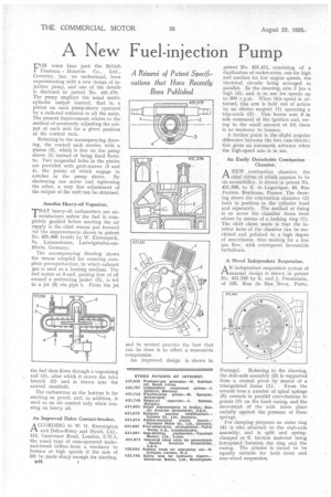
E-OR some time past the British 1 Thomson Houston Co., Ltd., Coventry, has, we understand, been experimenting with a new design of injection pump, and one of the details is disclosed in patent No. 491,479. The pump employs the usual multicylinder output control, that is, a pinion on each pump-sleeve operated by a rack-rod common to all the units. The present improvement relates to the method of accurately adjusting the output of each unit for a given position of the control rack. Referring to the accompanying drawing, the control rack meshes with a pinion (2), which is free on the pump sleeve (1) instead of being fixed thereto. Two tangential holes in the pinion are provided with grub-screws (3 and 4), the points of which engage in notches in the pump sleeve. By slackening one screw and tightening the other, a very fine adjustment of the output of the unit can be obtained.
Another Heavy-oil Vaporizer.
THAT heavy-oil carburetters are unsatisfactory satisfactory unless the fuel is completely gasified before meeting the air supply is the chief reason put forward for the improvements shown in patent No. 431,466 (void) by W. Ehrenspeck, 8a, Luisenstrasse, Ludwigshafen-amRhein, Germany. The accompanying drawing shows the means adopted for ensuring complete prevaporization, in which exhaust gas is used as a heating medium. The fuel enters at 4 and, passing first of all around a preheating jacket (5), is fed to a jet (6) via pipe 1. From the jet the fuel then flows through a vaporizing coil (3), after which it enters the inlet branch (2) and is drawn into the central manifold. The carburetter at the bottom is for starting on petrol, and, in addition, is used as an air control only when running on heavy oil.
An Improved Delco Contact-breaker.
A CCORDING to W. 0. Kennington 1-1. and Delco-Remy and Hyatt, Ltd., 111, Grosvenor Road, London, &WA, the usual type of cam-operated makeand-break suffers from a tendency to bounce at high speeds if the rate of lift be made sharp enough for starting, 844 • patent No. 111,411, consisting of a duplication of rocker-arms, one for high and another for low, engine speeds, the electrical circuits being arranged in parallel. In the drawing, arm 3 has a high lift, and is in use for speeds up to 200 r.p.m. When this speed is attained, this arm is held out of action by an electro magnet (1) operating a trip-catch (2). This leaves arm 4 in sole command of the ignition and, owing to the small amount of lift there is no tendency to bounce. A further point is the slight angular difference between the two cam-blocks; this gives an automatic advance when the high-speed arm is in use.
An Easily Detachable Combustion Chamber.
A' ■ W combustion chamber, the
chief virtue of which appears to be its accessibility, is shown in patent No. 431,396, by E. de Lagarrigue, 40, Rue Ferrere, Bordeaux, France. The drawing shows the combustion chamber (2) both in position in the cylinder head and separately. The method of fixing is to screw the chamber down from above by means of a locking ring (1). The chief claim made is that the interior faces of the chamber can be machined and polished, to a high degree of smoothness, thus making for a free gas flow, with consequent favourable turbulence.
A Novel Independent Suspension.
AN independent suspension system of unusual design is shown in patent No. 431,249 by E. and J. Ferreirinha, of 125, Rua da Boa Nova, Porto, Portugal. Referring to the drawing, the stub-axle assembly (2) is supported from a central pivot by means of a triangulated frame (1). From the n central boss a umber of spiral springs (5) extends in parallel convolutions to th points (3) on e fixed casing, and the movement of the axle takes place radially against the pressure of these
springs, os o
For damping purposes an outer ring stub-axle 4) is also attached to the
m
assembly, and is split and springclamped at 6, friction material being ring interposed between the ng and the The scheme is stated to casing. be equally suitable for both front and rear-wheel suspension.