


Workshop ways
Page 29
Page 30
If you've noticed an error in this article please click here to report it so we can fix it.
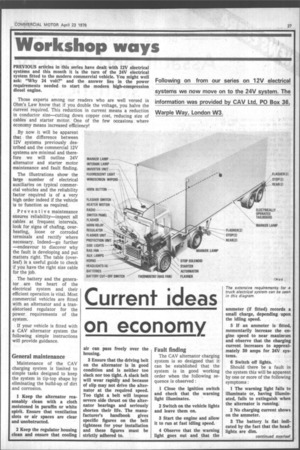
PREVIOUS articles in this series have dealt with 12V electrical systems and this month it is the turn of the 24V electrical system fitted to the modern commercial vehicle. You might well ask: "Why 24 volt?" and the answer lies in the power requirements needed to start the modern high-compression diesel engine.
Those experts among our readers who are well versed in Ohm's Law know that if you double the voltage, you halve the current required. This reduction in current means a reduction in conductor size—cutting down copper cost, reducing size of cables and starter motor. One of the few occasions where economy means increased efficiency!
By now it will be apparent that the difference between 12V systems previously described and the commercial 12V systems are minimal and therefore we will outline 24V alternator and starter motor maintenance and fault finding.
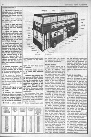
The illustrations show the large number of electrical auxiliaries on typical commercial vehicles and the reliability factor required is of a very high order indeed if the vehicle is to function as required.
Preventive maintenance ensures reliability—inspect all cables at frequent intervals, look for signs of chafing, overheating, loose or corroded terminals and rectify where necessary. Indeed—go further —endeavour to discover why the fault is developing and put matters right. The table (overleaf) is a useful guide to check if you have the right size cable for the job.
The battery and the generator are the heart of the electrical system and their efficient operation is vital. Most commercial vehicles are fitted with an alternator and a transistorised regulator for the power requirements of the system.
If your vehicle is fitted with a CAV alternator system the following simple instructions will provide guidance.
General maintenance
Maintenance of 'the CAV charging system is limited to simple tasks designed to keep the system in tip-top shape by eliminating the build-up of dirt and corrosion.
I Keep the alternator reasonably clean with a cloth moistened in paraffin or white spirit. Ensure that ventilation slots or air spaces are clear and unobstructed.
2 Keep the regulator housing clean and ensure that cooling air can pass freely over the housing.
3 Ensure that the driving belt on the alternator is in good condition and is neither too slack nor too tight. A slack belt will wear rapidly and because of slip may not drive the alternator at the required speed. Too tight a belt will impose severe side thrust on the alternator bearings and seriously shorten their life. The manufacturer's handbook gives specific figures on the belt tightness for your installation and these figures must be strictly adhered to.
Fault finding
The CAV alternator charging system is so designed that it can be established that the system is in good working order when the following sequence is observed : I Close the ignition switch and check that the warning light illuminates.
2 Switch on the vehicle lights and leave them on.
3 Start the engine and allow it to run at fast idling speed.
4 Observe that the warning light goes out and that the ammeter (if fitted) records a small charge, depending upon the idling speed.
5 If an ammeter is fitted, momentarily increase the engine speed to near maximum and observe that the charging current increases to approximately 30 amps for 24V systems.
6 Switch off lights.
Should there be a fault in the system this will be apparent by one or more of the following symptoms : I The warning light fails to illuminate or, having illuminated, fails to extinguish when the alternator is running.
2 No charging current shows on the ammeter.
3 The battery is flat indicated by the fact that the headlights are dim. 4 The battery is "boiling "indicating loss of voltage control and accompanied by continuously high charge rate on the ammeter.
If any of these symptoms are present the fault can be located as follows : I Check all leads and connections for visible faults such as a battery lead adrift. Replace If required.
2 Check the warning light bulb filament and holder, and fit a new bulb if the filament is broken. If a new bulb is fitted then check the system again as detailed in the first part of Fault Finding.
3 If the bulb and holder are serviceable and still no light appears, then switch off and disconnect the lead on the F terminal of the regulator. Clip this lead to the negative terminal on the regulator. Switch on the ignition switch. If the light now appears, then the regulator is faulty and a new regulator is required. If no light appears, then the alternator is faulty and requires workshop attention.
4 Having determined the location of the fault, switch off and reconnect the 'F' lead to its correct position on the 'F' terminal of the regulator.
If the battery is " boiling " and a continuously high charge rate shows on the ammeter (if fitted), this usually indicates loss of voltage control and this may be determined by the following test : I Obtain a first-grade moving coil voltmeter scaled in 0-50 volt range.
2 Connect the voltmeter between the battery or regulator negative terminal (marked -) and the regulator positive terminal (marked HI, MED or LO) in use on the installation.
3 Switch on all the vehicle
Compare the truck layout with this ' psv especially on the lighting system.
lights and leave them on for 3-5 minutes.
4 Start the engine and run it at about half maximum speed.
5 Observe the voltmeter and the ammeter (if fitted). Switch off the vehicle lights. Depending on the connection in use (HI, MED or LO), the voltage should rise to between 26 and 28.5V on a 24V system and then remain constant. After a short time the current reading on the ammeter should drop considerably.
Any divergence from these figures indicates the regulator is defective and a new regulator is required. When testing the equipment, never disconnect a running alternator.
Do not attempt repairs with out skilled help, the correct test equipment and the essential technical information.
Starter motors
The starter motor on a modern commercial vehicle is in fact, a powerful highefficiency intermittently rated electric motor and because of its power output has a high current rating. Almost without exception the pinion engages with the flywheel ring gear by means of an axial movement of the pinion operated by a solenoid either mounted internally or on the top of the starter motor. The following recommendations apply particularly to CAV starter motors.
Lubrication : The drive end bearing is lubricated by a wick contained in a large oil reservoir in the drive-end shield. The capacity of this reservoir is such that it requires no attention during routine maintenance, but should be refilled when the starter is dismantled at major overhaul periods. However, in cases where the starter is not subjected to regular overhauls, the reservoir must be replenished at intervals of not more than two years. This should be done by removing the starter and removing the core plug in the drive end shield. Add a supply of Shell Tellus T27 oil through the oil filler hole exposed. A new core plug must be fitted when oiling is completed.
Cables and mounting bolts : The starter should be examined to ensure that its mounting bolts are securely fastened, and that all cable connections are clean and tight. The cables should also be inspected for fractures particularly at the point where the cable enters the terminal lug. The cable insulation should be free from chafing or deterioration due to oil.
Faults in operation
If the starter does not operate or is sluggish in operation when the starter button is pressed, check to see that the battery is in a fully charged condition. A simple test is to switch on the vehicle lights and then operate the starter button. If the lights maintain full brilliance, check the switch and battery connections to the starter and all external leads.
The main battery connection to the starter should be secure. If it becomes loose it may well swivel round and short circuit across the solenoid terminal. This will result in the starter operating and being held into mesh, should this occur whilst the engine is running, the starter and the ring gear will suffer serious damage.
To avoid undue brush and commutator wear, care should be taken to prevent the entry of oil or fuel into the starter.
Following the simple preventive maintenance recommended here ensures that commercial electrical equipment will give an excellent service life. If major repairs are ever required, these should be handled by the manufacturer's franchised agents.