


A Resume of Recently Published Patent Specifications
Page 50
If you've noticed an error in this article please click here to report it so we can fix it.
An Improved Gully Emptier.
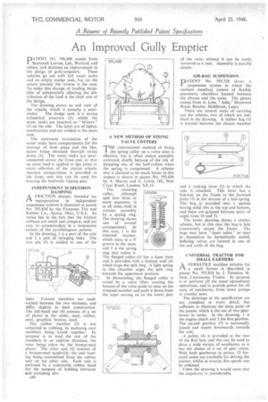
DATENT No. 596,486 comes from Scammeli Lorries, Ltd., Watford, and others, and discloses an improvement in
the design of gully-emptiers. These vehicles go out with full water tanks and an empty sludge tank, but on the return journey the reverse is the case. To make this change of loading incapable of substantially affecting the distribution of the load is the chief aim of the design.
The drawing shows an end view of the vehicle, which is actually a semi trailer. The sludge tank is a strong cylindrical structure (1), whilst the water tanks are attached as "blisters" (2) on the side. The fatter are of lighter construction and are welded to the main tank.
The outermost extremities of the water tanks have compartment i for the stowage of hose pipes and the like, access being obtained through swing doors (3). The water tanks are interconnected across the front end, so that an extra load is applied at tbis point to assist adhesion of the tractor wheels. Another compartment is provided at the front, and this can be used for housing the hydraulic tipping gear.
INDEPENDENT SUSPENSION DAMPING
ai FRICTION damper intended for j ai FRICTION damper intended for j incorporation in .independent suspension systems is disclosed in patent No. 595,830 by the Firestone Tire and Rubber Co., Akron, Ohio, U.S.A. Its virtue lies in the fact that the friction surfaces are small and compact, and are easy to accommodate in a suspension system of the parallelogram pattern.
In the drawing, 1 is a part of the axle and 2 a pair of swinging links. The axis pin (3) is welded to one of the inks. Friction members are sandwiched between the two elements, and differ slightly in their construction. The left-hand one (4) consists of a set of plates in the order, steel, rubber, steel, graphitic bronze, steel.
The rubber member (5) is not subjected to rubbing, its enclosing steel members being keyed together. Its purpose is to load the rest of the members in an endwise direction, the wear being taken by the bronze-steel plates. The other unit (6) consists of a bronze-steel sandwich, the end loading being transmitted from the rubber unit on the other side. Each unit is enclosed by a contractile rubber band for the purpose of holding lubricant and excluding dirt. A NEW METHOD OF FIXING VALVE COTTERS THE conventional method of fixing
I the spring collar on a valve stem is effective, but it often makes assembly awkward, chiefly because of the risk of dropping one of the half-collars when the spring is compressed. A scheme that is claimed to be much better in this respect is shown in patent No. 595,696 by A. Martin and A. Lewis, 182, New Cross Road, London, S.E.14.
The retaining collar, although split into threeor more segments, is at all times held in circular assembly by a spring ring.'
The drawing shows one of several arrangements. In this case, I is the trisected retainer, which seats in a V groove in the stem, and 2 is the sPring ring that unites it.
The flanged collar. (3) has a taper bore and is provided with a bottom wall (4) which traps the split ring: A light spring in this Chamber urges the split ring towards the uppermost position.
In dismantling, the flanged collar is raised by a valve lifter, causing the bottom of the valve guide to abut on the trisected member and push it down from the taper seating on to the lower part 593696 of the stem, whence it can be easily removed as a unit. Assembly is equally simple.
AIR-BAG SUSPENSION
DATENT No. 595,728 shows a suspension system in which the resilient members consist of flexible pneumatic chambers located between the chassis and the axles. The patent comes from A. Lees, "Aida," Heywood Road, Bowlee, Middleton, Lancs. There are several ways of carrying out the scheme,, two of which are outlined in the drawing. A rubber bag (I) is located between the chassis member
and a rocking lever (2) to which tht axle is attached. This lever has a fulcrum on the frame at the forward point (3) in the manner of a leaf-spring. The bag is moulded into a section having solid ribs at the top and bottom, and these are gripped between pairs of angle irons (4and 5).
The lower drawing shows a similar scheme, but in this case the bag is laid transversely across the frame. The bags may have "inner tubes" or may in themselves be hermetically sealed. Inflating valves are located in one of the end walls of the bag.
UNIVERSAL TRACTOR FOR SMALL FARMERS
Pl.A VERSATILE machine suitable for a small farmer is described in patent No. 595,826 by J. Teisseire, St. Jean, Carcassone, France. Its purpose is to perform all the usual agricultural operations, and to provide power for all sorts of auxiliaries, from water pumps to circular saws.
The drawings in the specification are not complete in every detail, but sufficient to illustrate the main point of the patent, which is the use of two gearboxes in series. In the drawing, I is the engine clutch and 2 the first gearbox. The second gearbox (3) is universally joined and slopeIs downwards to-wards the axle.
A pulley (4) is provided at the rear Of the first box, and this can be used to drive a wide variety of auxiliaries, as it has the choice of a set of gear ratios. With both gearboxes in action, 12 forward ratios are available for driving the tractor, whilst in reverse, five speeds can be obtained.
From the drawing it would seem that the angularity is considerable.