A New Van Body Design T HE trend of modern vehicle
Page 62

If you've noticed an error in this article please click here to report it so we can fix it.
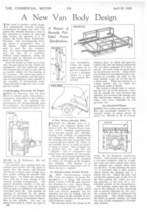
design is undoubtedly towards one-piece construction for frame and body, and patent No, 462,622 discloses a step in this direction in respect of vans and light lorries; the patentee is J. P. Garner, 46, Priory Road, Kenilworth, Warwick. The accompanying drawing shows a perspective view of the scheme. Light channel-section steel is used for the construction, two main longitudinals, joined near the rear by a cruciform stiffener being employed, whilst the forward ends are upswept for attachment to the motive unit.
Steel box-frames are built up on each side, leaving spaces for the wheels and mudguards, and the additional space thus formed may be used, in the case of an electric vehicle, for the housing of the batteries: The frame thus made is standard for all vehicles, and the operation of bodybuilding is thus reduced to the. assembly of standardized units. These are made in jigs and vary in only exterior details.
A Self-charging Two-stroke Oil engine.
SINCE the discovery that the mass exit of exhaust gases will produce a momentary depression in the cylinder, several schemes for utilizing this phenomenon for charge-inducing have been proposed. An arrangement of this nature forms the subject of patent No.
462,288, by M. Kadenacy, 120, rue Lecourhe, Paris.
The pressure wave passing from the exhaust port travels with the speed of sound, and, like sound, will rebound and set up a return wave of high pressure, partly refilling the cylinder with burnt gases. To utilize the principle, then, calls for a close timing of the exhaust porting arrangements. The present invention consists of the employment of a rotary valve (2) in the exhaust pipe, in addition to -the pistoncontrolled ports (3). The moment of opening is governed by the piston descent, but the rotary valve closes the port at the instant of maximum depress sion in the cylinder. The new air enters from ports 4, which are open to
A36 the atmosphere, whilst the mushroom valve (1) is part of a scheme of super charging shown in a previous patent No. 447,537.
A New Refuse-collection Body.
PATENT No. 462,859, from A. J. Biland and Hygienic Refuse Con tainers, Ltd., 39, Victoria Street, London, S.W.1, discloses improvements on a previous patent (No. 446,006) dealing with methods of compressing and transporting refuse. Referring to the drawing, the body is provided with a power-operated piston (2) which, in the position shown, is ready to receive a charge of refuse. This is tipped via a pivoted flap (1), falls into the " cylinder " and is compressed and moved into the interior by the piston.
The basis of the present patent is the use of an endless band (3), mounted on rollers, for the floor of the compression chamber. This feature, it is claimed, facilitates compression, and reduces the power required.
An Injection-pump Control System.
ANEW injection-pump control forms the subject of patent No. 462,898 by G. J. Trapp, 105, Aylward Road, London, S.W.20, and Automotive Products Co., Ltd., Brock House, Longhorn Street, London, W.1. The scheme is applicable to pumps fitted with two control members, one for quantity and one for timing, and the patent is based on the methods of linking these two members to the governor and accelerator pedal.
The drawing shows the scheme .in -its
simplest form, • in which the quantity control (Q) and the timing adjustment (T) are each connected to a lever (1 and 6), the lower ends of which meet on the governor, rod (3). 'These levers are mounted on movable fulcrums comprising an eccentric (5) and, on the same spindle, a pin (2) on the end of a. short arm. These are carried by a central spindle (4), to which ths accelerator pedal is linked.
The action is clearly seen by assuming the rod (3) to be stationary; turning the spindle (4) then increases the quantity and advances the timing, and this relationship remains at the new value, even when controlled by the governor rod.
An Articulated Piston.
IMPROVED cooling and lessened wear lore the advantages claimed for the unusual design of piston shown in patent No. 462,644 by R. de Champ bonin, 19, rue Berthelot, Courbevoie, France. This inventor proposes to use a two-piece assembly, that is, a series rate head and skirt, joined only about the gudgeon pin, around which they are pivoted. In the drawing, the head (1) is provided with a stem portion which carries the gudgeon pin in a forked end (3). Inside the fork, and around the gudgeon pin, is the boss of the skirt portion (2), which, for cooling purposes, is cut away for a considerable portion of its circumference.
The inventor claims that the thrust due to the obliquity of the connecting rod is entirely absorbed by the skirt, the wearing of which is comparatively unimportant. The forces acting on the head are purely vertical, and thus the wear on this component is considerably reduced.


