SIMPLE MECHANICS
Page 60

If you've noticed an error in this article please click here to report it so we can fix it.
FINAL DRIVES, 4
• by Preceptor
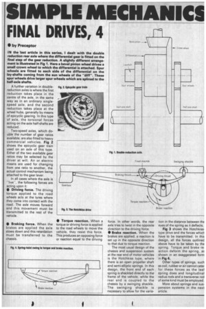
IN the 'last article in this series, I dealt with the double reduction rear axle where the differential gear is fitted on the final step of the gear reduction. A slightly different arrangement is illustrated in Fig 1. Here a bevel pinion wheel drives a small crown wheel to which the differential is attached. Spur wheels are fitted to each side of the differential on the lay-shafts coming from the sun wheels of the "diff". These spur wheels drive larger spur wheels which are splined to the half-axle shafts.
A further variation in doublereduction axles is where the first reduction takes place in the centre of the axle, in the same way as in an ordinary singlespeed axle, and the second reduction takes place at the wheel hubs, generally by means of epicyclic gearing. In this type of axle, the torsional forces acting on the axle half-shafts are reduced.
Two-speed axles, which double the number of gear ratios available, are also fitted to heavy commercial vehicles. Fig 2 shows the epicyclic gear train used on an axle of this type. Either of the two available gear ratios may be selected by the driver at will. Air or electric means are used for changing from one ratio to another, the actual control mechanism being attached to the gear lever.
In all cases where the axle is "live", the following forces are acting upon it: 110 Driving force. The driving torque applied to the road wheels acts at the tyres where they come into contact with the road. The axle moves forward and this movement must be transmitted to the rest of the vehicle.
• Braking force. When the brakes are applied the axle slows down and this retardation must be transferred to the chassis • Torque reaction. When a torque or driving force is applied to the road wheels to move the vehicle, they resist this force. This produces an opposing force or reaction equal to the driving force. In other words, the rear axle tries to twist in the opposite direction to the driving force.
• Brake reaction. When the brakes are applied, a reaction is set up in the opposite direction to that due to torque reaction.
The most usual design of the chassis and suspension system at the rear end of motor vehicles is the Hotchkiss type, where there is an open propeller shaft and semi-elliptic springs. In this design, the front end of each spring is shackled directly to the frame of the vehicle, while the rear end is coupled to the chassis by a swinging shackle. The swinging shackle is necessary to allow for the varia
tion in the distance between the eyes of the spring as it deflects.
Fig 3 shows the Hotchkiss type drive and the forces which have to be transmitted. In this design, all the forces outlined above have to be taken by the spring. Torque and brake re• action deform the spring, aE shown in an exaggerated form in Fig 4.
Other types of springs, such as coil, rubber or air cannot cater for these forces as the leaf spring does and longitudinal radius rods and a transverse rod of some kind must be employed.
More about springs and suspension systems in the next article.


