Wire-net and Fabric Body Construction
Page 48

If you've noticed an error in this article please click here to report it so we can fix it.
A Résumé of Recently Published Patent Specifications Obtainable from the Patent Office, Price is. each
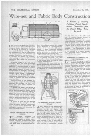
DISCLOSED in patent No. 511,561, in the names of Lever Brothers and Unilever, Ltd., Bla,ckfriars, London, E.C.4, and J. B. Walton, is a scheme for a method of body building combining lightness with ease of replacement of damaged parts and resistance to damage from minor road accidents. It is proposed to employ as covering, wire netting, a layer of felt-covered cardboard and ,sheets of waterproof canvas. A specific design for a 5-ton van is described. Back and front are formed respectively by the cab and a roller blind (1). The main hoops, of which there are six, are composed of vertical light metal channels (3 and 4), one being inserted in the other, with anglesection horizontals. Cross-pieces (8) support these hoops. Longitudinal members (5 and 6) space them apart. In addition, wooden slats (7) are provided to protect the body covering from the' load. Equal in width to the distance between hoops, strips of wire covering material are arranged in line with these, the ends being attached to longitudinals 5. Of about 2-in, mesh, the netting is fixed by screws to wooden blocks (9) in the uprights and by similar means to the horizontals. Over the netting is placed the felt-covered cardboard (10), in double width and with the felt outermost. Outside this is placed a single sheet of waterproof canvas (11), Metal panels complete the lower parts of the sides. A feature is that the wire netting contributes to the strength of the whole, so lighter material than normal may be used for the framework. An alternative method of attaching the wire is by spot welding.
METAL DEPOSITION ON ALLOY PISTONS.
,THE extreme lightness of magnesium-alloys renders . them particularly suitable for piston manufacture, although, owing to their poor wearing qualities it is necessary to provide some form of-wear-resisting cur
face.
face. According to patent No. 510,404 by 11. Berghaus, 31 Charlottenstrasse, Berlin, it is extremely difficult to obtain a good adherence between magnesium and other metal, and the patent proceeds to describe a satisfactory method of achieving this. The scheme is to place the piston in a vacuum chamber where it is heated by an electric discharge, and then bombarded with a shower of molecules of the plating, metal by what is called cathode disintegration.
Thicknesses of from .005 in. to several millimetres can be deposited by this method, and it may be of metal chosen for its hardness or its resistance to corrosion, pr a combination of these characteristics,
AKEY feature of the Aspin engine the subject of patent No, 511,208, by F. M.Aspin, 149, Walmersley Road, Bury, It relates to the bearings, lubrication and sealing effect of the conical rotary valve (1) This comprises a ported steel shell (2) having an aluminium core. There is a short cylindrical portion at each end. The valve shaft runs in tapered roller bearings (3 and 4) which are designed to take one-third of the maximum load due to combustion. A third race (5) takes part of the radial loading. A constant upward pressure is maintained by the spring 6. Dining peak pressures the normal yield of bearing 3, although extremely small, is greater than that of the oil film between the conical valve. surfaces. Thus the races are protected from overloading, whilst high friction is of short duration. This combination of antifriction bearing and oil film is claimed by the inventor to be highly satisfactory, provided correct clearance be established at the outset.
TORSION-BAR APPLIED TO VALVE-SPRING.
"rORSION-BAR springing is applied 1 to internal combustion engine valves in patent No. 511,272, by Construction Mecaniques du Beam, Jurancon-Pan (13asses-.Pyrenees), France. The resilient unit comprises a torsion bar (I) and a sleeve (3), the former carrying an arm (2). Trunnioned to the forked, end of rocker 6, which is actuated in the usual manner by a push rod (8) and pivoti on pin 7, is a block (5) working in a slot (4) in the enlarged valve stem. Force to close the valve is transmitted with an advantageous ratio from arm 2 to rocker 6 by a thrust piece (9), grooves being provided to receive its radiused ends. Adjustment of the degree of force is permitted by the splines on the torsion bar.


