


Rear-wheel Assembly for Vlulti-Wheelers
Page 90
If you've noticed an error in this article please click here to report it so we can fix it.
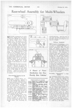
MOUNTING arrangements for multiwheeled vehicles form the subject of patent No. 471,621 by G. Mackay, 10. Queen Anne's Grove; Ealing, . London,W.5. The scheme is a compromise. between the four-wheel-iv-line andthe twin-axle types, the term "echelon mounting" being employed.
The accoMpanying drawing shows a plan of half the vehicle, -and' clearly illustrates the disposition of the wheels. Each wheel is carried on a stub axle (3) attached to the end of a rocking beam. The beam is pivoted in the middle in two directions, on a cross
wise axia for the rocking motion, and in a direction parallel with the frame for road-camber adjustment. A pro. jecting aim (2), pivoted on a resiliently mounted bracket (1) on the centreline of the chassis, controls the rocking motion ; the opposite side of the assembly . is alsoattached in a similar manner.
As illustrated,. the system is for trailing wheels only, but the patent also describes a driving arrangement in which axle shafts are led to the centre of the rocking beams, the drive being taken to the wheels by chains and sprockets. These are housed inside the beams, which are made hollow for the purpose.
Bosch Starting Vaporizer for Oil Engines.
THE name of Robert Bosch, A.G.. Stuttgart,' Germany, appears in patent. No. 471,582 which describes a fuel-vaporizing device intended to assist the starting of oil engines. The general scheme is shown in the drawing. A pipe (4) leads from a constant-level fuel reservoir (3) to the air intake of the engine, where it terminates in a
small nozzle (1). An electric heater coil (5) is wound around the tube in the regias of the fuel level, and vaporizes the fuel, which passes into the air stream via the nozzle.
An important feature of the invention is the auto-regulation of the amount of vapour. If this tends to become excessive, its pressure forces the fuel downwards and out of the heating region, thus decreasing the A36 amount generated. Note the small air inlet (2) ; this limits the suction on the fuel tube, thereby preventing the passing over of liquid.
Built-up Crankshaft.
THE expense of machining a crank' shaft is a constant inducement, to inventors to devise some more expedient construction; such a scheme forms the subject of patent No. 471,513 by Armstrong Siddeley Motors, Ltd., and L. F. Fell, both of Park Side, Coventry. The crankshaft ix assembled from units, the basic piece being a member (1) consisting of a pin bearing and two opposed crankpins. Crankpin 2 is tubular, whilst crankpin 3 comprises a pin portion of a size less than the actual running diameter. The pin portion of one end is the counterpart of the bore at the other, so that a shaft of any desired number of units can be assembled. The method of uniting the components is described in the patent as a "push fit,” although splines may be used if desired.
• The bolts and conical washers shown in the centre of each journal are purely for the enclosure of oil spaces, and play no part in the assembly.
Preventing " Diesel-knock " at Slow Speeds.
A CONTROLLABLE device employ
ing a spring-loaded cylinder head ts shown in patent No, 471,428, by G. Fitt and P. Mason, both of Tankerton Garage, Tankerton, Kent. The object is to provide a means for absorbing the heavy shocks occurring in an oil engine when running at low speed.
Referring to the accompanying drawing, the cylinder head consists of a . secondary piston held down on to a conical seating (4) by spring pressure, which is controlled by a cam (2) on a spindle carrying a lever (1). Movement of the cam adjusts the pressure of spring 3 and thus varies the amount of lift during the power stroke. An essential feature of the patent is the attachment of a governor to lever 1, arranged so that the lowest spring pressure is applied during idling, increasing to a solid lock at full speed,