


Patents Completed.
Page 20
If you've noticed an error in this article please click here to report it so we can fix it.
FILES.—Neill.—No. 12,916, dated 17th June, 1908.—According to this invention a file is provided with continuous cutting edges (13) arranged at an angle, the apex of which is in the centre of the file. This arrangement tends to part the material abraded, and thereby reduce the labour of operating the file. The shape of The teeth also tends to balance the file so as to prevent it running off laterally without cutting and also to avoid "c-battering" by preventing the teeth of the file following into consecutive cuts.
IMPROVED PUMP.—Markt and Belli. -No. 20,291, dated 11th September, 1907, —This invention relates to combined rotary and reciprocating pumps for
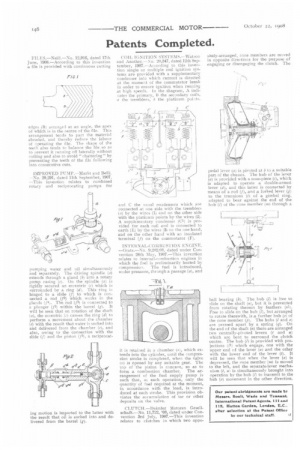
pumping water and oil simultaneously and separately. The driving spindle (a) extends through a gland (b) into a rotary pump casing (e). On the spindle (a) is rigidly secured an eccentric (r) which is surrounded by a ring (d). This ring is hinged to a slide (1) to which is connected a rod (t2) which works in the glands (f4) The rod (f2) is connected to a plunger (jl) within the barrel (g). It will be seen that on rotation of the shaft (a), the eccentric (r) causes the ring (d) to perform a movement about the chamber (e) with the result that water is sucked into and delivered from the chamber (e), and also, owing to the connection with the slide (I) and the piston (ft), a reciprocat ing motion is imparted to the latter with the result that oil is slicked into and delivered from the barrel (g). ( :OIL IGNITION SYST EN1 S.– -Watson and Another.—No. 20,347, dated 12th September, 1907.—According to this invention single or multiple coil ignition systems are provided with a supplementary condenser into which current is directed at the moment of the commutator break in order to ensure ignition when running at high speeds. in the diagram, A indicates the primary, 11 the secondary coils, a the tremblers, b the platinum points.
and the usual coadensers which are
connected at one side with the tremblers (a) by the wires (1) and on the other side with the platinum points by the wires (2). A supplementary condenser (C1) is provided for each coil arid is connected to earth (E) by the wires (3) on the one hand, and on the other hand with an insulated terminal (j) on the commutator (F).
INTERNAL-COMBUSTION ENGINE. —Grate.—No. 9,21-'!2108, dated under Convention 24th May, 1907.—This invention relates to internal-combustion engines in which the fuel is preliminarily heated by
compression. The fuel is introduced, under pressure, through a passage (a), and
it is retained in a chamber (,), which extends into the cylinder, until the compression stroke is completed, when the valve (a) is opened by any suitable gear. The top of the piston is concave, so as to form a combustion chamber. The arrangement of the fuel supply pump is such that, at each operation, only the quantity of fuel required at the moment, in accordance with the load, is introduced at each stroke. This provision obviates the accumulation of tar or other deposits on the valve.
CLUTCH.—Daimler Motoren Gesellschaft.—No. 11,722, '08, dated under Convention 3rd July, 1907.—This invention relates to clutches in which two oppo
sitely-arranged, cone members are moved in opposite directions for the purpose of engaging or disengaging the clutch. The
pedal lever (a) is pivoted at b to a suitable part of the chassis. The hub of the lever (a) is provided with a nose-piece (e), which is adapted to operate a double-armed lever (d), and this latter is connected by means of a rod (A and a forked lever (g) to the trunnions (i) of a gimbal ring, adapted to bear against the end of the hub (I) of the cone member (m) through a ball bearing (k). The hub (I) is free to slide on the shaft (a), but it is prevented from rotating thereon by feathers (nle. Free to slide on the hub (I), hut arranged to rotate therewith, is a further hub (a) of the cone member (el. The hubs Cl and al are pressed apart by a spring (q). On the end of the shaft (a) there are arranged two centrally-pivoted levers (t and a) which arc bent to surround the clutch centre. The hub (/1 is provided with projections (A) which engage, one with the upper end of the lever (al and the other with the lower end of the lever (t). It will bo seen that when the lever (a) is depressed, the 'one member (m) is moved to the left, and the separate-lever mechanism (I, a) is simultaneously brought into operation by the hub (1) to transmit to the hub (a) movement in the other direction.