


Transmission Gear Repairs for Tractors.
Page 18
Page 19
If you've noticed an error in this article please click here to report it so we can fix it.
By an Engineer-in-Charge.
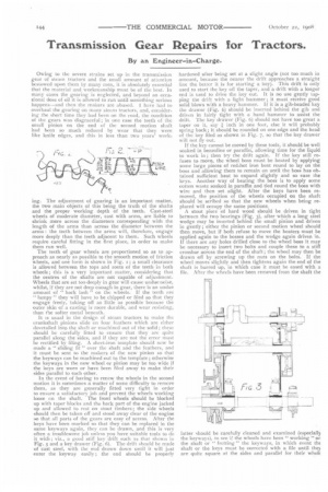
Owing to the severe strains set up in the transmission gear of steam tractors and the small amount of attention bestowed upon them by many men, it is absolutely essential that the material and workmanship must be of the best. In many eases the gearing is neglected, and beyond an occasional dose of oil it is allowed to run until something serious happens—and then the makers are abused, have had to overhaul the gearing on many steam tractors, and, considering the short time they had been on the road, the condition of the gears was disgraceful; in one vast the teeth of the small pinion on the end of the second motion shaft had been so much reduced by wear that they were like knife edges, and this in less than two years' work ing. The adjustment of gearing is an important matter, the two main objects of this being the truth of the shafts and the proper working depth of the teeth. Cast-steel wheels of moderate diameter, cast with arms, are liable to shrink more across the diameters corresponding with the length of the arms than across the diameter between the arms : the teeth between the arms will, therefore, engage more deeply than the teeth adjacent to them. Such wheels require careful fitting in the first place, in order to make them run well.
The teeth of gear wheels are proportioned so as to approach as nearly as possible to the smooth motion of friction wheels, and one form is shown in Fig. 1; a small clearance is allowed between the tops and roots of the teeth in both wheels ; this is a very important matter, considering that the centres of the shafts are not capable of adjustment. Wheels that are set too deeply in gear will cause undue noise, whilst, if they are not deep enough in gear, there is an undue amount of " back lash " on the wheels. If the teeth are " lumpy "they will have to be chipped or filed so that they engage freely, taking off as little as possible because the outer skin of a casting is more durable, and wear resisting, than the softer metal beneath.
It is usual in the design of steam tractors to make the crankshaft pinions slide on four feathers which are either dovetailed into the shaft or machined out of the solid ; these should be carefully fitted to ensure that they are quite parallel along the sides, and if they are not the error must be rectified by filing. A sheet-iron template should now be made a "sliding fit " over the shaft and the feathers, and it must be sent to the makers of the new pinion so that the keyways can be machined out to the template; otherwise the keyways in the new wheel or pinion may be too wide if the keys are worn or have been filed away to make their sides parallel to each other.
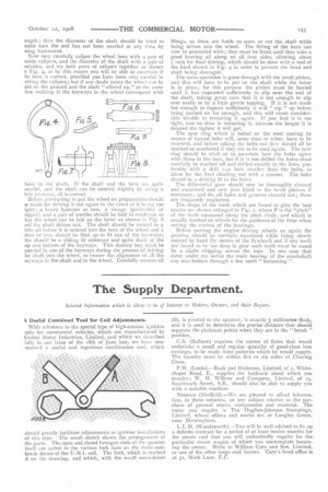
In the event of having to renew the wheels in the second motion it is sometimes a matter of some difficulty to remove them, as they are generally fitted very tight in order to ensure a satisfactory job and prevent the wheels working loose on the shaft. The front wheels should be blocked up with taper blocks and the back part of the engine jacked up and allowed to rest on stout timbers ; the side wheels should then be taken off and stood away clear of the engine so that all parts of the gears are easy of access. After the keys have been marked so that they can be replaced in the same keyways again, they can be drawn, and this is very often a troublesome job unless you have suitable tools to do it with ; viz., a good stiff key drift such as that shown in Fig. 5 and a key drawer (Fig. 6). The drift should be made of cast steel, with the end drawn down until it will just enter the keyway easily ; the end should be properly hardened after being set at a slight angle (not too much in amount, because the nearer the drift approaches a straight line the better it is for starting a. key). This drift is only used to start the key off the taper, and a drift with a longer end is used to drive the key out. It is no use gently tapping the drift with a light hammer ; it must receive good solid blows with a heavy hammer, If it is a gib-headed key the drawer (Fig. 6) should be inserted behind the gib and driven in fairly tight with a hand hammer to assist the drift. The key drawer (Fig. 6) should not have too great a taper on it, say inch in one foot, else it will probably spring back ; it should be rounded on one edge and the head of the key filed as shown in Fig. 7, so that the key drawer will not tly out. If the key cannot be moved by these tools, it should be well soaked in benzoline or paraffin, allowing time for the liquid to work in ; then try the drift again. If the key still refuses to move, the wheel boss must be heated by applying some large pieces of red-hot iron bent round to lay on the boss and allowing them to remain on until the boss has obtained sufficient heat to expand slightly and so ease the keys. Another way of heating the boss is to apply some cotton waste soaked in paraffin and tied round the boss with wire and then set alight. After the keys have been removed, the position of the wheels occupied on the shaft should be scribed so that the new wheels when being replaced will occupy the same positions.
A stout piece of hard wood should be driven in tight between the two bearings (Fig. 3), after which a long steel wedge may be inserted behind the small pinion and driven in gently ; either the pinion or second motion wheel should then move, but if both refuse to move the heaters must be applied again to the bosses and the wedge again driven in. If there are any holes drilled close to the wheel boss it may he necessary to insert two bolts and couple these to a stiff crossbar across the end of the shaft ; the wheel may then be drawn off by screwing up the nuts on the bolts. If the wheel moves slightly and then tightens again the end of the shaft is burred up, in which case it must be eased with a file. After the wheels have been removed from the shaft the
latter should be carefully cleaned and examined (especially the keyways), to see if the wheels have been " working "on the shaft or " fretting " the keyways, in which event thf shaft or the keys must be corrected with a file until they are quite square at the sides and parallel for their whok
ength ; then the diameter of the shaft should be tried to nake sure the end has not been swelled at any time by leing hammered.
Now very carefully caliper the wheel bore with a pair of nside calipers, and the diameter of the shaft with a pair of utsides, and try both pairs of calipers together as shown n Fig. , as by this means you will be able to ascertain if he bore is correct, provided you have been very careful in etting the calipers; but if any doubt exists the wheel van be aid on the ground and the shaft "offered up," at the same ime noticing if the keyways in the wheel correspond with
hose in the shaft. If the shaft and the bore are quite arallel, and the shaft can be entered slightly by using a ittle pressure, all is correct.
Before attempting to put the wheel on preparations should )e made for driving it out again in the event of it being too ight ; a heavy hammer or two, a swage (preferably of opper), and a pair of trestles should be held in readiness so hat the wheel can be laid on the latter as shown in Fig. 8 tnd the shaft driven out. The shaft should he treated to a itHe oil before it is entered into the bore of the wheel and a &cc of iron should be filed up to fit one of the keyways ; his should be a sliding fit sideways and quite slack at the op and bottom of the keyways. This dummy key must be nserted in one of the keyways during the process of driving he shaft into the wheel, to ensure the alignment of all the teywavs in the shaft and in the wheel. Carefully remove all filings, as these are liable to score or cut the shaft while being driven into the wheel. The fitting of the keys can now be proceeded with; they must be fitted until they take a good bearing all along on all four sides, allowing about j1. inch for final driving, which should be done with a tool of the kind shown in Fig. 9 in order to prevent the head and shaft being damaged.
The same operation is gone through with the small pinion, and this will have to be put on the shaft while the latter is in place; for this purpose the pinion must be heated until it has expanded sufficiently to slip over the end of the shaft, taking great care that it is hot enough to slip over easily or by a little gentle tapping. If it is not made hot enough to expand sufficiently it will " nip " up before being pushed on far enough, and this will mean considerable trouble in removing it again. If you find it is too tight, lose no time in removing it, because the longer it is delayed the tighter it will get.
The spur ring which is bolted on the steel casting by means of turned bolts will, some time or other, have to be renewed, and before taking the bolts out they should all be marked or numbered if they are to be used again. The new ring should be tried on to ascertain how the holes agree with those in the buss, but if it is not drilled the holes must carefully he marked off and drilled exactly to the lines, preferably with a drill i-32 inch smaller than the bolts, to allow for the. final cleaning out with a reamer. The bolts should he a driving fit in the holes.
The differential gear should now be thoroughly cleaned and examined and new pins fitted to the bevel pinions if necessary; and the oil holes and grooves cleaned out; these are frequently neglected.
The shape of the teeth which are found to give the best results are shown enlarged in Fig. 2, where P is the "pitch" of the teeth measured along the pitch circle, and which is usually marked on wheels for the guidance of the fitter when setting the centres of the bearings.
Before putting the engine driving wheels on again the gearing should be carefully examined while being slowly rotated by hand (by means of the flywheel) and if any teeth are found to be too deep in gear such teeth must be eased by a slight chipping across the tops. In one case that came under my notice the main bearing of the crankshaft cap was broken through a few teeth "bottoming."