


A Hydro-mechanical Transmission DATENT No. 783,995 shows a
Page 58
If you've noticed an error in this article please click here to report it so we can fix it.
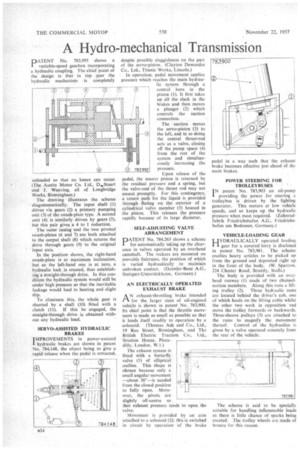
variable-speed gearbox incorporating a hydraulic coupling. The chief point of the design is that in top gear the hydraulic mechanism is completely unloaded so that no losses can occur. (The Austin Motor Co. Ltd., D.Stuart and J. Weaving, all of Longbridge Works, Birmingham.) The drawing illustrates the scheme • diagrammatically. The input shaft (1) drives via gears (2) a primary pumping unit (3) of the swash-plate type. A second unit (4) is similarly driven by gears (5), but this pair gives a 4 to 1 reduction. The outer casing and the two pivoted swash-plates (6 and 7) are both attached to the output shaft (8) which returns the drive through gears (9) to the original input axis.
In the position shown, the right-hand swash-plate is at maximum inclination, but as the left-hand one is at zero, a hydraulic lock is created, thus establishing a straight-through drive. In this condition the hydraulic system would still be under high pressure so that the inevitable leakage would lead to heating and slight slip.
To eliminate this, the whole gear is shunted by a shaft (10) fitted with a clutch (11). If this be engaged, the straight-through drive is obtained without any hydraulic load.
SERVO-ASSISTED HYDRAULIC BRAKES IMPROVEMENTS in power-assisted I hydraulic brakes are shown in patent No. 784,148, the object being to give a rapid release when the pedal is retracted,
despite possible sluggishness on the part of the servo-piston. (Clayton Dewandre Co., Ltd., Titanic Works, Lincoln.) In operation; pedal movement applies pressure which reaches the main hydraulic system through a central bore in the piston (1). It first takes up all the slack in the brakes and then moves a plunger (2) which controls the suction connection.
®
The suction moves the servo-piston (3) to the left, and in so doing the central thrust-rod acts as a valve, closing off the pump space (4) from the rest of the system and simultan
Yi) 783995 eously increasing the
pressure.
Upon release of the pedal, the master piston is returned by the residual pressure and a spring, but the valve-end of the thrust rod may not unseat promptly. For this contingency, a return path for the liquid is provided through fluting on the exterior of a cylindrical valve member (5) housed in the piston. This releases the pressure rapidly because of its large diameter.
• SELF-ADJUSTING VALVE ARRANGEMENT
PATENT No. 784,265 shows a scheme for automatically taking up the clearance in valves operated by an overhead camshaft. The rockers are mounted on movable fulcrums, the position of which is varied hydraulically to maintain unbroken contact. (Daimler-Benz A.G.. Stuttgart-Untertiirkheim, Germany.)
AN ELECTRICALLY OPERATED EXHAUST BRAKE
AN exhaust-throttling brake intended for the larger sizes of oil-engined vehicle is shown in patent No. 783,900. Its chief point is that the throttle movement is made as small as possible so that it lends itself readily to operation by a solenoid. (Thomas Ash and Co., Ltd., 19 Rea Street, Birmingham, and Tit,: British Electric Traction Co., Ltd., Stratton House, Picca dilly, London, W.1.)
The exhaust system is fitted with a butterfly valve (1) of elliptical outline. This shape is chosen because only a small angular movement —about 30"—is needed from the closed position to fully open. Moreover, the pivots are slightly off-centre so that exhaust pressure tends to open the valve.
Movement is provided by an arm attached to a solenoid (2); this is switched in circuit by operation of the brake pedal in a way such that the exhaust brake becomes effective just ahead of the main brakes.
POW ER STEERING FOR TROLLEYBUSES
N patent No. 783,903 an oil-pump I providing the power for steering a trolleybus is driven by the lighting generator. This motors at low vehicle speeds, and so keeps up the hydraulic pressure when most required. (Zahnradfabrik Friedrichshafen A.G.. Friedrichshafen am Bodensee, Germany.)
VEHICLE-LOADING GEAR
HYDRAULICALLY operated loading I I gear for a covered lorry is disclosed in patent No. 783,981. The scheme enables heavy articles to be picked up from the ground and deposited right up in the front of the body. (W. Sparrow. 224 Chester Road, Streetly, Staffs.)
The body is provided with an ov;:rhead runway (1) made of two channelsection members. Along this runs a lifting trolley (2). Three hydraulic rams are located behind the driver's cab, one of which hauls on the lifting cable whilst the other two work in opposition and move the trolley forwards or backwards. Three-sheave pulleys (3) are attached to the rams to magnify the movement thereof. Control of the hydraulics is given by a valve operated remotely from the rear of the vehicle.
The scheme is said to be specially suitable for handling inflammable loads as there is little chance of sparks being created. The trolley wheels are made of bronze for this reason.