


Mechanical Horse-Power:
Page 30
Page 31
If you've noticed an error in this article please click here to report it so we can fix it.
What It Is, and How It Is Measured. (Concluded from page 228).
The Electrical Brake Test.
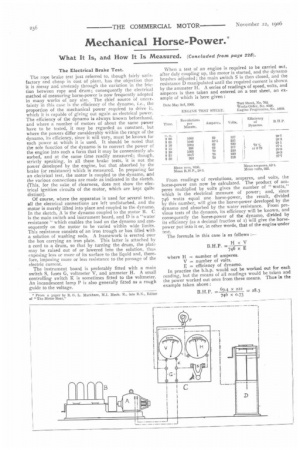
The rope brake test just referred to, though fairly satisfactory and cheap in cost of plant, has the objection that it is messy and unsteady through the variation in the friction between rope and drum; consequently the electrical method of measuring horse-power is now frequently adopted in many works of any size. The chief source of uncertainty in this case is the efficiency of the dynamo, i.e., the proportion of the mechanical power required to drive it, which it is capable of giving out again as electrical power. The efficiency of the dynamo is always known beforehand, and where a number of motors of about the same power have to be tested, it may be regarded as constant, but where the powers differ considerably within the range of the dynamo, its efficiency, since it will vary, must be known for each power at which it is used. It should be noted that the sole function of the dynamo is to convert the power of the engine into such a form that it may be conveniently absorbed, and at the same time readily measured; though, strictly speaking, in all these brake tests, it is not the power developed by the engine, but that absorbed by the brake (or resistance) which is measured. In preparing for an electrical test, the motor is coupled to the dynamo, and the various connections are made as indicated in the sketch. (This, for the sake of clearness, does not show the electrical ignition circuits of the motor, which are kept quite distinct).
Of course, where the apparatus is used for several tests, all the electrical connections are left undisturbed, and the motor is merely lifted into place and coupled to the dynamo. In the sketch, A is the dynamo coupled to the motor B. C is the main switch and instrument board, and D is a "water resistance " which enables the load on the dynamo and consequently on the motor to be varied within wide limits. This resistance consists of an iron trough or box filled with a solution of washing soda. A framework is erected over the box carrying an iron plate. This latter is attached by a cord to a drum, so that by turning the drum, the plate may be raised out of or lowered into the solution, thus exposing less or more of its surface to the liquid and, therefore, imposing more or less resistance to the passage of the electric current.
The instrument board is preferably fitted with a main switch S, fuses G, voltmeter V, and ammeter H. A small controlling switch K is sometimes fitted to the voltmeter. An incandescent lamp P is also generally fitted as a rough guide to the voltage. When a test of an engine is required to be carried out, after duly coupling up, the motor is started, and the dynamo brushes adjusted ; the main switch S is then closed, and the resistance D manipulated until the required current is shown by the ammeter H. A series of readings of speed, volts, and amperes is then taken and entered on a test sheet, an example of which is here given : Date May Srd, 1906. Test Sheet, No. '7112.
From readings of revolutions, amperes, and volts, the horse-power can now be calculated. The product of amperes multiplied by volts gives the number of " watts," which is the electrical measure of power; and, since 746 watts equal one horse-power, the result, divided by this number, will give the horse-power developed by the dynamo and absorbed by the water resistance. From previous tests of the dynamo, its efficiency will be known, and consequently the horse-power of the dynamo, divided by its efficiency (as a decimal fraction of s) will give the horsepower put into it or, in other words, that of the engine under test.
The formula in this case is as follows :— In practice the b.h.p. would not be worked out for each reading, but the means of all readings would be taken and the power worked out once from these means. Thus in the example taken above :
It should be noted that the number of revolutions of the engine does not enter directly into this formula ; it is, however, an essential factor upon which the electrical readings depend, and is thus indirectly taken account of It will, therefore, be seen that the horse-power recorded is that of the engine at the revolutions (or the mean revolutions) at which it was taken.
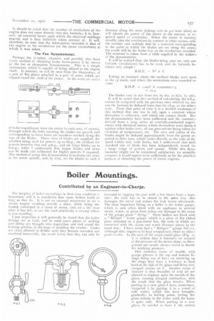
The Fan Dynamometer.
Perhaps the simplest, cleanest, and possibly also least costly method of obtaining brake horse-power is by means of the fan or absorption dynamometer. This is a simple instrument, which is capable of being affixed to the engme shaft. It consists, as will be seen from the illustration, of a pair of flat plates attached to a pair of arms, which are clipped round the ..haft of thr motor. In the arms are series of holes (equidistant from the centre in each arm, of course), through which the bolts securing the blades are passed, and corresponding to these holes are numbers marked along the tops of the blades. Three sizes of blades are supplied, the smallest being used for powers up to 6h.p., the medium for powers between that and 3oh.p., and the large blades up to oolep., while I understand that larger blades and arms can be made and calibrated for higher powers if required. The method of using this dynamometer is to clamp the arms to the motor spindle, and, bv trial, set the blades to such a distance along the arms (taking care to get both alike) as will absorb the power of the motor at tne normal, or required speed of revolution. When the motor is running steadily take the revolutions by counter or other means, cube the number and multiply that by a constant corresponding to the point at which the blades are set along the arms; the result will be the brake h.p. at the revolutions recorded. The constant is taken from a table supplied by the makers of the dynamometer.
It will be noticed that, the blades being once set, only one variable (revolutions) has to be read, and the formula becomes very simple :
B.H.P. N3 X C
Taking an instance where the medium blades were used at the 15 mark, and where the revolutions were recorded as
1,000
B. H. P. i,000?. x m0000000 13
= 11.3 The blades vary in sire from bin, by bin, to by 17in.
It will be noted that this method of calculating the b.h.p. cannot be compared with the previous ones referred to, nor can the fornutla be deduced from that for i.h.p. as the others were. From that point of view it is a decided weakness of this method that one has to rely upon a constant whose derivaliOn is unknown, and which one cannot check. But the dynamometers have been calibrated and the constants derived from a long series of carefully-conducted experiments with electrical motors which themselves were checked against other brake tests, all due precautions being taken for variation of temperature, etc. The area and radius of the blades might be deduced approximately from the power required to drive fans, which varies directly as the cube of thespeed within very wide limits, but I understand that each standard size of blade has been independently tested for a large range of powers and speeds. While this dynamometer might not be considered satisfactory for scientific purposes it would appear to be sufficiently so for the practical purpose of obtaining the power of motor engines.