


Steam as a Motive Power for Public Service Vehicles.
Page 3
Page 4
If you've noticed an error in this article please click here to report it so we can fix it.
The selection of the motive power for public service vehicles must be considered in its relationship to the public safety and convenience, as well as with respect to the " state of the art," or in relation to the development of any particular type of motor. It has been commonly supposed that steam was unsuitable for omnibus propulsion, and if one assumes the ordinary methods of steam generation and application to be used, this conclusion is probably correct. The question arises : Is one justified in assuming that the ordinary methods of steam generation and application represent its highest practical possibilities? One object of this paper is to show that this is by no means the case, and that recent developments in the methods of harnessing :..team for public service have entirely altered the situation, and have brought within one's grasp the important advantages peculiar to steam which, apart from the question of their realisation, are generally admitted. From the history of steam on common roads, it appears that the first steam omnibus in London was constructed and run by Hancock about the year 183o. Further developments were hindered for many years by legislation until the repeal of the " Red Flag " Act in 1896. Steam omnibuses have been constructed on the Continent by Serpollet, De Dion, Scone, and others. About 1897 Mr. H. A. House constructed several omnibuses which were fired with liquid fuel. A service was commenced with these cars in thoucestershire between Fairford and Cirencester, but did not prove successful. The next steam omnibus appears to have been constructed by Messrs. Thornycroft, and was put into service on the Hammersmith route by the Road Car Co., about 1902. This car was an ordinary heavy chassis fitted with plain steel tires and fired with coke, to which a double-deck omnibus body was attached. The author understands that it was commercially successful, but tfiat it was in other respects found to be unsuitable to the conditions of public service in London. in particular the fumes and dust of the coke fuel were objectionable to the passengers, and the weight and the steel tires did not conduce to silent running.
The next development in steam omnibuses appears to have been the inauguration of the service at Torquay. This
was started in 1903, and the service has up to the present time worked very successfully. These cars were designed by the author, and are of the single-deck type, fired with paraffin. Similar cars were subsequently tried in London, and ran for about a year. One service by the Road Car Co., from Oxford Circus to Hammersmith, and another by the London General Omnibus Co., from Hammrsmith to Piccadilly Circus. These cars had seating capacity for 14 passengers, which did not compare favourably in earning power with the double-deck bus seating 34 passengers. Independently of the great discrepancy in their earning capacity, it is found that a distinct preditection exists among a large section of the public to " see Loadon from the top of a bus." Seeing that the public taste ran parallel to the commercial interests of the omnibus companies, it is natural that the double-deck omnibus was soon selected as the best type for London service. In 1905 the first double-deck steam omnibus of the author's construction commenced regular service in London, and at present there are about 40 licensed by the police for :erviee in London. About WO ot these vehicles have already been made.
The advantages of steam for public service work may Le generally summarised as follows The employment of a safe and cheap fuel. Freedom from noise and vibration.
Absence of smell.
Smooth and silent action of the machinery.
Quick acceleration without jerkiness. Flexibility of drive and simplicity of control. Large reserve power for hills and for overcoming the inertia of starting.
rs' Entire absence of change-speed gears.
Entire absence of electric ignition.
Entire absence of friction-clutch.
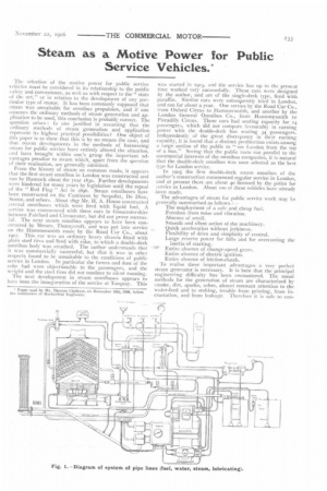
To realise these important advantages a very perfect steam generator is necessary. It is here that the principal engineering difficulty has been encountered. The usual methods for the generation of steam are characterised by smoke, dirt, sparks, ashes, almost constant attention to the water-feed and to stoking, trouble from priming, from incrustation, and from leakage. Therefore it is safe to con
dude that the usual methods of steam generation arc unsuited for the purpose. To produce a generator free from the above vices, and which is regular and reliable in action, has proved a most serious problem. It is surprising to many engineers to find that steam can be generated automatically as required, without any of the preceding drawbacks, and that the generator, instead of being a delicate thing needing careful handling and attention, has been made robust and healthy, and, for all practical purposes, " fool-proof."
For the purpose of description, the generator may be divided into three parts, namely, the burner (Fig. 2), the boiler (Fig. 4), and the governing gear (Figs. 6 and 7).
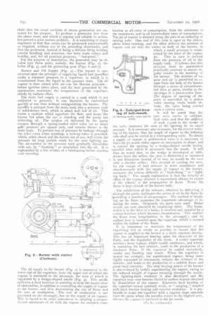
Burner and Oil Supfily (Fig. 4—The burner is constructed upon the principle of supplying liquid fuel (paraffin) under a constant pressure to a vaporiser, in which it is transformed from the liquid to the gaseous state. The oil vapour is then mixed with air—on the Bunsen principle— before ignition takes place, and the heat generated by the combustion maintains the temperature of the vaporiser, chiefly by radiant effect.
The main fuel supply is carried in a Lank which is not subjected to pressure, it can therefore be replenished quickly at any time without extinguishing the burner. The paraffin is pumped from the main tank into a pressure tank of solid-drawn steel, which is about half full of air. This forms a cushion which equalises the flow, and keeps the burner fed when the car is standing and the pump not delivering oil. The surplus oil delivered by the pump escapes through a spring-loaded relief valve set to about 4o1b. pressure per square inch, and returns thence to the main tank. To prevent loss of pressure by leakage through the relief valve when standing, a lock-up valve is provided, which, when closed and the burner out of use, will retain the pressure for long periods ready for the next lighting up. The air-cushion in the pressure tank gradually diminishes with use, by " foaming " or absorption into the oil. It is replenished by a few strokes of a hand-pump before starting each morning.
The oil supply to the burner (Fig. 2) is connected to the lower end of the vaporiser, from the upper end of which the vapour is conveyed to the jet-nozzle, the area of which is regulated by a wedge-shaped needle (Fig. 3). This needle performs a dual function in assisting to keep the nozzle clear of obstruction, in addition to controlling the supply of vapour to the burner, and thus determining the size of flame and the rate of combustion. The rate of combustion is not governed on the oil-supply, but on the supply of oil vapour. This is found io be more convenient in securing a proportionate admixture of air with the vapour for complete corn bustion at all rates of consumption, from the minimum to the maximum, and at all intermediate rates of consumption. The jet of vapour is directed along the axis of an inducing or mixing tube. One end of this tube is open to the atmosphere when running, and the other delivers the mixture of vapour and air into the centre or body of the burner, in which a small pressure is maintained by the force of the vapour jet. This in turn is derived from the pressure of oil in the supply tank. It follows that this pressure must be maintained practically constant to ensure regular results in the working of the burner. The mixture of vapour and air is permitted to escape from the body of the burner
los3 through a series of circumferential slots or ports, similar to the openings in a piston-valve liner. The degree of opening of the /as. ports is controlled by 'a piston. 2 3 valve moving freely inside the body, the valve being carried upon a central stem.
It will be noted that the port area varies in arithmetical ratio, and that the addition of each I-32nd to the stroke of the valve increases the area of the opening by an equal amount. IL is necessary also to ensure, for the correct working of the burner, that the supply of vapour to the inducing tube shall also be varied in a corresponding ratio. To obtain a supply of vapour in arithmetical ratio it is necessary to form the jet nozzle either square or rectangular in shape, and lo control the opening by a wedge-shaped needle having -parallel sides which fit accurately into the nozzle. It will thus be noted that, as the wedge is introduced or withdrawn from the orifice, the area is diminished or increased in one dimension instead of in two, as would be the case with a circular orifice. This method of varying the area, for the escape of fuel mixture in strict accordance and simultaneously with the supply of vapour to the burner, overcame the serious difficulty of " back-firing " or "
back." The simple explanation is that the velocity of efflux of the vapour mixture is maintained always in excess of the velocity of the propagation of flame. ifence the flame is kept outside of the burner body.
The subdivision of the mixture, obtained by delivering it through the ports, facilitates the access of air to the flame by -providing a number of air-passages. The method of breaking up the flame possesses the important advantage of reducing the noise. Originally six ports were used. Better results are now obtained by employing thirty. The flame, which is in the form of a basin, is received and steadied by a conical frustum which becomes incandescent. This shelters the flame from irregularities in the air-supply; and its radiant heat is focussed upon the vaporiser, which is located within the hollow of the flame.
It is important to maintain the temperature of the vaporising coil as evenly as possible to ensure that the vapour is supplied to the burner at a fairly constant density. This has an important bearing upon the character of the flame, and the regularity of the work. A cooler vaporiser produces dense vapour, which readily condenses, and which, by enriching the fuel mixture, tends to the production of a luminous flame. If the vapori.er be cooled excessively, smoke and flooding may result. When the vaporiser is heated too strongly, the superheated vapour, being more highly expanded or attenuated, reduces the richness of the mixture, and tends to the production of a reddish flame and great local intensity. The total heating power of the burner is also reduced by unduly superheati-ng the vapour, owing to the reduced weight of vapour escaping through the nozzle. The lighting-back tendency is also developed and the vaporiser may soon become fouled by carbon deposit obtained by dissociation of the vapour. Excessive local heating of the vaporiser means unsteady work, or " surging," coupled with local interior fouling and exterior oxidation. It is preferable to make the vaporiser with a regular slope upwards from the point where the paraffin enters to the highest part, whence the vapour is conveyed to the jet nozzle.
Fig. 3. — Enlarged drawing of bell-mouth.
(A) showing needle valve and sir Pump.