


Cylinder-pressure-powered Injection
Page 68
If you've noticed an error in this article please click here to report it so we can fix it.
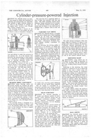
PATENT No. 810,502 shows an injection system in which the functions of metering and pressurizing are separated. This permits a light, accurate pump to be used as the pressure is created by the engine itself. (C.A.V., Ltd., Warple Way, Acton, London, W.3.)
The drawing shows a layout of the scheme in which 1 is the pump, the duty of which is only to measure a charge of fuel and deliver it under low pressure to the injector (2). It is the injector that performs the pressurizing; a small piston (3) is subjected to cylinder compression and in • moving upwards works the injector plunger via a rocker (4)....
In detail, the arrival of fuel at the injector moves a valve plunger (5) downwards to close a passage (6) leading to the nozzle tip. The fuel then unseats a spring-loaded valve (7) and passes upwards into the pumping space (8). On the succeeding suction stroke of the pump, the valve plunger re-opens the passage simultaneously with the descent of the pressure plunger (9) and injection follows. When the cylinder pressure falls the plunger is returned by its spring in readiness for the next cycle.
BEARING SHELL ALIGNMENT DIG-END plain bearing shells are I—) usually located by making the bolts which secure the bearing caps a close fit in .their holes. This imposes close manufacturing tolerances on the diameter of both the bolts and the holes. Patent No.810,617 shows a scheme in which the bearing shells locate themselves in the connecting rod eye, so that the bolt-to-hole tolerance ceases to be important, giving a consequent reduction in manufacturing cost. (Ford Motor Co., Ltd., 88 Regent Street, London, W.1.)
The drawing shows a fragment of a big-end bearing assembly in which 1 and 2 are the bearing shells and 3 the bolthole; in this instance the hole is tapped and a screw is used. The joint line (4) is angularly offset so that it does not -coincide with the cap joint. The shell assembly cannot move sideways, being restrained by its circular fit. To prevent rotation of the shells, a dowel may be fitted, or one shell may be dimpled into a shallow hole in the rod or cap.
VARIABLE FAN DRIVE
PATENT No. 810,659 shows a variable fan drive which uses a fluid coupling operated by 'oil from the lubricating system. The unit is said to give a smooth action as the fluid drive eliminates noise and shock. (Thompson Products Inc., 23555 Euclid Avenue, Cleveland 17, Ohio, U.S.A.)
In the drawing, the driving pulley is connected to an impeller (1) whilst the driven turbine (2) is attached to the fan spindle. When oil from the engine is pumped into the fluid coupling, drive is established progressively until the unit is filled, at which point maximum drive is attained. Intermediate filling gives intermediate speeds due to coupling slip. The coupling casing is sealed by a washer (3) and the ingress of oil compresses the air inside thus ensuring quick discharge to reduce the fan speed when required.
The oil supply is controlled by a thermally operated valve which responds to the temperature of the cooling water; this unit is also described in the patent.
PILOT INJECTION
DATENT No. 810,456 describes a I simple and efficient method of introducing a pilot injection charge into an oil engine combustion chamber. (The British internal Combustion Engine Research Association, 111-112 Buckingham Avenue, Slough.)
The drawing shows a partial section of the upper part of an ejection pump. In its general principles the pump is conventional, quantity being adjusted by the helical edge (1) on the plunger. The novelty consists of a spring-loaded piston-valve (2) in the discharge line.
In operation, when the plunger rises, fuel pressure lifts the piston valve and cuts off an escape port (3) leading back to the fuel supply via a passage (4). Further movement causes fuel trapped in the blind space (5) to pass through the hollow piston and reach the discharge port through a cross-bore (6). This constitutes the pilot injection. • The pilot charge terminates when the upper edge of a. groove (7) opens to the escape port and so releases all pressure. Continued upward movement of the piston gives a short idle period until the bottom of the piston uncovers the main outlet (8), after which the main discharge takes place. A restriction in the fluid path on the return stroke gives a dashpot action which brings the piston valve to rest at the bottom without shock.
SERVICING RAMP
I—I A SERVICING ramp which can be
tilted to any angle is described in patent No. 810,592. (K. W. Paulus and Co., Ltd., 10 Bury Place, Strand, London, W.C.1.) Referring to the drawing, the ramp comprises a platform (1) on to which the vehicle is run over a fixed ramp (2). Instead of being pivoted on trunnions, the platform swings on a spherical bearing (3) with roller bearings interposed to reduce friction. The geometric centre of the arcs and therefore the pivoting axle is located in mid-air above the platform, at a point approximating to the centre of gravity of the combined platform and vehicle. This means that tilting demands little effort and, in the most favourable circumstances, the vehicle would "stay put" at any angle.
A further scheme shows the platform fitted with a second rocking mechanism at right angles to the first, so that it acts as a universal joint to give side tipping. Another patent, numbered 810,593, deals with the means used for chocking the vehicle in position.
BALL JOINTS
PATENT No. 810,330 shows a ball joint intended for steering systems. The socket is a deep drawn member having a spherical portion for the ball and an upper tubular extension that can be screwed and used as a point of attachment. The patent comes from V. Langen, Hansa-Allee 190, DusseldorfOberhassal, Germany.