


Pump to Give Pilot Injection
Page 58
If you've noticed an error in this article please click here to report it so we can fix it.
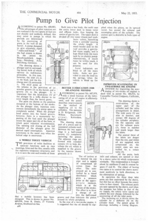
A CCORDING to patent No. 688,003, ri the advantages of pilot injection are not realized if the two spurts of fuel are not sharply and suddenly defined; this may occur in pumps in which the periods are determined. by the uncovering of ports in the wall of the barrel. A pump designed to give extremely rapid " make-and-break " of the fuel stream is shown in the patent by Maschinenfabrik Augsburg Nurnberg Niirnberg, Germany.
The drawing shows a plunger and its surrounding barrel, both of which operateon well-known principles. In this case, however, the inlet (1). is in the head, and the discharge port (2) surrounds it. The chief point of the scheme is the provision of an annular groove (3) in the barrel. and .a 'groove (4) in the plunger. • It is important that the head-piece (5)of the plunger be a trifle shorter in its axial length than the barrel grove.
The parts are shown in the position occupied at the bottom of the stroke. As the plunger rises, injection commences immediately the pump space is completely -sealed. When the plunger head passes into the barrel groove, however, there is a momentary bypas'sing of the fuel until the plunger enters the upper part (6) of the bore, at which point injection re-conimences. The opening and closing of the full' diameter of the plunger gives the desired rapid interruption. Injection terminates in the usual way when the
helical edge is uncovered. , A MOBILE TOILET VEHICLE
THE provision of toilet facilities at open-air functions such as race meetings, fetes and the like, usually calls for expensive temporary structures, and it is to save the cost and trouble of these
that a mobile lavatory has been designed. This is shown in patent No. 689,050, from R. Drake, 27 Victoria Avenue, Southend-on-Sea.
Built into a bus body, the outfit uses the entire lower deck to house water and effluent tanks, thus keeping the centre of gravity low. The upper deck is divided off into water closets and washbasin cabins, branching from a corridormincing the whole length. A small header tank on the roof provides a gravityfed water supply, and is kept filled from the main tank by an electric pump. Alternatively,, if mains , water be within reach, it can be used for this purpose.
688.003
Level indicators are fitted te• all the main tanks. Jacks are provided to ease the load on the springs, when the vehicle is fitted up for use,
BETTER LUBRICATION FOR OIL-ENGINE PISTONS
A CCORDING to patent No. 687,979, rli•only a small fraction of the lubricating oil of an oil engine is efficiently used, and the patent describes improvements in the method of supplying oil to the cylinders. The patentee is D. ICrijgsman, 139b
Willem Buytewech s t r a a t, Rotterdam, Holland. • The drawing shoals part of a piston and its associated cylinder-wall. Between the two upper rings is a half-round groove (1) completely encircling the piston. The adjacent rings are formed with rounded corners (2) to help distribute the oil, which is supplied to the groove by the injector shown generally at 3.
The oil arrives at the injector via one pipe and a supply of compressed air comes from the other. The compressed air is controlled by a timed distributor which gives a pressure pulse at the appropriate moment, which is at the bottom of the stroke. The effect is to blow a charge of oil into the half-round groove and thus lubricate the piston around its whole periphery.
In the case of a two-stroke engine, it is suggested that the oil should be sup
plied when the piston, on its upward travel, has passed the exhaust and scavenging ports of the cylinder. The coolest spot is desirable in both types of engine.
IMPROVED SCAVENGING IN TWO-STROKE OIL ENGINE
1-1 A SYSTEM for improving the scavenging of tvio-stroke oil engines is dealt with in patent No. 686,914, by 'Caterpillar Tractor Company, California, U.S.A.
The drawing shows a cross-section of the upper part of the cylinder and thevalve arrangements in detail. The inlet ports (1) are nine in number, and occupy 180 degrees Of the cylinder periphery. On the opposite side are the exhaust ports (2), three in number and much larger than the inlets.
The central three of the inlets are deeper than the rest, and whilst all are supplied with compressed air, the centre ones are controlled by a rotary valve (3).
All the ports, both inlet and exhaust, are opened or shut by a sleeve valve (4) which reciprocates vertically. The reciprocation is brought about by camfaces (5 and 6) rotated by gears (7 and 8). The object of having two cams is to control the sleeve movement positively in both directions, to the elimination of springs.
In operation the three deep inlet ports are first uncovered by the sleeve, but this has no effect because the rotary valve is then closed. The exhaust ports are next opened by the sleeve, and when the pressure has fallen to that of the air supply, the rotary valve opens and admits the new charge, followed by the uncovering of all the inlet ports.
The incoming air is driven down the cylinder by a deflector (9) on the cylinder head. The patent gives 10 drawings including a timing diagram.