


Goodscontainer Loading System
Page 54
If you've noticed an error in this article please click here to report it so we can fix it.
A Resume of Recently Published Patent Specifications
ACOMPLETE outfit for loading and unloading goods containers from an articulated vehicle is described in patent No. 445,239 by A. P. Crescent, 23, rue Raynouard, Paris. In this scheme the container rests on a small frame, to the corners of which are attached swivelling wheels (1), each provided with a locking arrangement. To the underside of the trailer is fixed an hydraulic jack (2), whilst a small winch (not shown) is fitted under each end of the platform.
To unload the container, the jack (2) is lowered; this lifts the trailer clear of the tractor which can then be driven away. The jack is next slowly lowered, after which the container can be run down the platform to the ground, under control of the winch. The loading operation is performed by reversing this process, An Unusual Rear-wheel Arrangement.
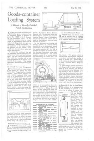
AN unorthodox scheme is put forward in patent No. 445,111 by Tatra Works, Ltd., Prague-Smichov, Czechoslovakia. This concern suggests that with vehicles equipped with twin tyres it is advantageous to arrange that at full loads both pairs of tyres are in use, whilst when running light the outer tyres alone carry the weight.
In the accompanying drawing, which shows the vehicle unloaded, each set of wheels is carried by an arm which presses against a transverse spring (1). The arms are pivoted as low as possible at points 3, and the wheel assemblies are once more pivoted at points 2 above the wheel centres. As shown, the inner tyres are almost clear of the ground, but application of a load would immediately bring both sets to bear.
Improved Torque-converter Control.
A SCHEME for an automatic control ..rt of the angular displacement of the reaction vanes of a torque-converter is shown in patent No. 444,171 by P. M.
1544 Salerni, 23, Carlton House Terrace, London, S.W. The patentee states that for this type of hydraulic gear, a speedoperated control alone is insufficient, and in the improved scheme use is made of the combined effects of rotation and oil pressure.
In the accompanying drawing, the driving member (I) and the driven member (8) are of substantially normal construction, the novelty residing in the reaction ,member (3). On this is mounted a number of movable vanes, the direction of movement being angular about central pivots. The control member consists of an annular piston 6) surrounding the central hub, and subject to oil pressure from the working space. Movement of this piston to the left operates a sliding sleeve (4) which, in turn, deflects the vanes via a series of arms (2). The pressure control is itself subject to centrifugal variation brought about by loose valves (7), which open or close a port (5) and so can regulate the pressure on both sides of the piston, according to the speed of the gear. See also patent No. 425,538. An Unusual Composite Piston.
APISTON which, it is claimed, need not be rejected after a cylinder rebore, is shown in patent No. 445,327 by G. Vassiliou, Rue Zangarol, Alexan
dria, Egypt. This piston, which is built up from several pieces, comprises a one-piece head and skirt having a flange at the top and a screwed flange at the bottom, so that when assembled it forms a cylinder with a flange at each end.
A piston ring is placed adjacent to each flange and the space between is filled up by a helically split tubular sIeeVe, as shown in the, drawing. The two portions of this are encircled by a coil spring, the tendency of which is to rotate them in the expansible direction. This, it is claimed ensures the correct value of endways pressure on the rings, and enables larger rings to be used after a rebore. It occurs to us that the extra weight may be a disadvantage.
All Improved Oil Seal for Axle Shafts,
rrHE problems of oil retaining and J. dirt excluding are claimed to be solved by a scheme in patent No. 445,308 by Super Oil Seal Manufacturing Co. (England), Ltd., Greet, Birmingham, and G. H. Ayres, 77, Castle Lane, Olton. The drawing shows an axle and housing embodying the invention, in which a leather ring (2), backed by a springy metal disc (1), is clamped between flanges formed on a ring (3) carried by the axle. An advantage claimed for the scheme is that dismantling and assembly of the shaft and housing does not affect the efficacy of the seal, the leather being held up against the housing bore by the springy disc.