


Patents Completed.
Page 28
If you've noticed an error in this article please click here to report it so we can fix it.
Complete specifications of the following patents will be sent to any address in the United Kingdom by the Sales Branch, Patent Office, Holborn, W.C., upon receipt of eightpence per copy.
A Novel Box Spanner.
r. A. Delacroix, No. 16,793, 1912— dated under International Convention, 22nd November,1911.—The main feature
of this invention is a screw key to be used with box spanners. The spanners or sockets themselves are of the usual form to fit the nuts, but they are quite short, and the round end is slotted on two diameters at right-angles to one another, as shown in the drawings. The key for turning the sockets consists of a hollow tube which serves as a handle, with the key fitted to one end. This key piece is made of a piece of steel of asection, in which there has been fixed a plate of the same thickness, at right-angles to its axis, thus giving a piece of the shape shown in the accompanying illustration. With this arrangement the view from any of the four sides, or from the end of the key piece, is a simple cross like that shown in the view of the key. It is obvious, therefore, that the key may bt used in a number of ways, two of which are shown in the illustration.
Types of Thrust Bearings.
H. G. Johnston, No. 28884913 dated under International Convention, 6th February, 1912.—In thrust bearings of the cone, rollk..r, or ball type, absolute accu
racy of machining is required to produce fittings in which the stress is uniformly distributed over all the thrust members. In order to obviate the necessity for such accurate work this thrust bearing is provided with a central fleeting ring. On one side of this a series of coned col
lars may be provided, and on the other aide a series of balls, as shown in the accompanying vertical section. The run-way for the cones is made of slightly greater length than the cones to permit of radial play, and the under side of this ring is given a spherical curvature. This spherical surface forms one side of the race for the balls, and the other side of the race is a similarly, curved ring secured to the bottom block. If the thrust on this bearing is unequally distributed in any way, the central floating ring, by reason of the curved race of the balls, travels to one side or the other, and assumes a slight inclination, so that it is normal to the direction of thrust, and all the cones and balls take an equal share of the load.
A Single Handle Brake-lever.
C. Stoppel, No. 2924/13, dated under International Convention, 7th February, 1912.—This brake-lever is one which erables the brake to be quickly applied and released by means of a single handle ; that is to say, it has no ratchet and
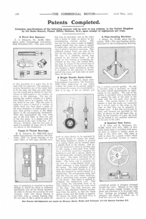
pawl or other device to be operated by a second handle to release the brake. The brake hand-lever proper is pivoted on a casing which can be rotated about a spindle fixed on the chassis. Just below the brake-lever there is pivoted, also on this casing, a bell-crank lever which has a toothlike projection engaging the brake-lever and also a spring, shown on the left-hand side, normally pressing the two apart. The upper left-hand end of this bell-crank lever is connected to the brake. The lower end is connected to one end of a wedge-shaped brake ring which embraces a ring mounted inside the casing. The inner periphery of this ring has ratchet teeth formed on it, and these are engaged by pawls located on a central disc ; the arrangement being such that the ring can only rotate clockwise. and is prevented from reverse rotation by the pawls. The brake is applied by swinging the brake-lever over. This first causes the bell-crank lever to be tilted slightly, so locking the brake band on the ring. The ring, however, can rotate in this direction without interfer. ence from the pawls, so that the whole casing swings and the brake is applied. To release the brake, the hand lever is moved in an opposite direction. A Pipe-bending Machine.
J., Huber, No. 27,849, dated 3rd December, 1912.—The pipe-bending device, illustrated in the accompanying drawing, has a central screwed spindle. On ths a two-arm yoke is mounted, on which the arms extend approximately at rightangles to one another. The end of the spindle is provided with a suitable hook to engage the pipe at the apex of the bend, and the two arms have similar honks. The special feature of this invention is that the hooks are connected by a swivel joint to the arms on the yoke, so that they can be adjusted in various ways. A flat disc swivel-joint is used, and recesses are provided in the disc, as shown on the left-hand side, so that, by the insertion of a pin, the hook can be locked it' any position relatively to the arm of the yoke.
A Sentinel Disc Valve.
S. E. Alley and R. McGregor, No. 16,203, dated 11th July, 1912.—A thin sheet metal plate is provided with annular slots to control a similar series of slots in the valve seat. The plate is held in place by a guard within which there are provided cavities to receive cylindrical guides or plungers arranged around the valve. Spigots on the ends of the plungers engage recesses in the plate, and maintain it in its proper position. Springs are arranged inside the plungers, the objects of which are to hold the valve on its scat.