


New Features in a Compact Four-speed Gearbox
Page 60
If you've noticed an error in this article please click here to report it so we can fix it.
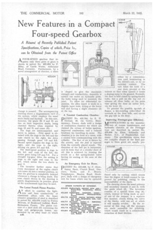
change is assured. The accompanying drawing shows a diagrammatic view of the system, which employs the usual main shafts and layshaft. In this case, however, the gears (9, 3 and 5) are free on their respective shafts, being clutched thereto when required by dogs (2 and 8) and cones (4).
. The dogs are interconnected, and move in unison. First speed is obtained with the dogs to the left and the cone 'clutch to. the .right, the drive passing through gears 1-9 and 6-5; Second speed requires the dogs to the right, and the cone to the right, driving via gears 3-7 and 64.
The third-speed position is dogs to the left and cone td the left, the active gears being 1-9 and 7-3. For a straight top-gear drive the setting is dogs to the right and cone to the left, which unites the two shafts in gear 3.
. The inventor further states that every movement of the engine clutch sets cones (4) into a neutral position, so that the gearbox is completely isolated whenever a change is being made. The cone clutch shown in the drawing is purely diagrammatic; in practice, gears of the synchromesh type may be used.
The Latest French Piston Practice.
A N effort to combine the lightness and heat conductivity of aluminium alloys with the lesser abrasive properties of steel is described in patent No. 423476 (void) by Fusion Moteurs, of Boulevard Gallieni, RueilMalmaison, France. The piston consists of a steel shell (3) containing the rings and gudgeon-pin bosses, surmounted by an alloy head (I) which B46, is shaped to give the maximum strength and conductivity. Assembly is carried out under an hydraulic press, the bolts being used to maintain the joint To allow for differential expansion, the alloy insert is made in a slightly taper form, fitting at the lower end and having a slight clearance (2) at the top.
A Toroidal Combustion Chamber.
PATENT No. 422,794, by E. H. Tartrais, 20, rue Gretry, Montmorency, France, deals with a design of combustion chamber for which are claimed the virtues of better ignition, improved combustion, and a reduced tendency for knocking to. occur. The chamber is in the form of a torus, with a central bore communicating with the cylinder. The flow of air is shown by the arrows, and the fuel is injected from the centrally placed nozzle. The direction of the fuel jet is horizontal, and its form that of a circular sheet of oil; this is achieved by forming the nozzle as a flat spring-loaded valve having its searing at the nose of the device.
An Emergency Exit for Buses.
PATENT No. 423,628, by F. Shaw, Sunny Bank, Church Road, Denthaw, Yorks, and F. Brown, Templestowe, Buxton Road, Stockport, deals with a design of emergency exit for buses which can be operated
either by a communication cord terminating in the driver's cab, or by an external control. The exit takes the form of a rear door, pivoted at the bottom so that when opened it forms a sloping ramp to the ground. Normally the door is held closed by spring-loaded bolts, but a pull on the top rod (1) releases all these bolts, at the ,same time giving the door an initial kick, via the lever (2).
To prevent the possible up-rush of flames, a fire-resisting roller-blind (3) unwinds as the door falls, and covers the gap left in the floor.
Improving Fiittinger-gear Efficiency.
AODIFICATIONS in the rnanufacIV/ ture of torque transformers and hydraulic clutches of the Fottinger type are described in patent No. 423,635 by Klein, Schanzlin and Becker, A.G., of Frankenthal, Germany. The specification states that the complex shapes of the fluid passages in these gears are usually pro duced only by casting, which means that the degree of finish cannot be improved by polishing, owing to the inaccessibility of the ducts.
The drawing shows the usual primary and secondary runners (1 and 2), with the guide wheel (3). The invention consists of a special inner ring (4), which, instead of being made as part of' one of the runners, is a separate free member, closely fitting the curve of the blades, with one set of which
it will usually revolve. By the removal of this ring, all the passages are made. accessible for polishing, which would result in a considerable reduction of fluid friction.