


Means for Supplying Heavy Fuel
Page 64
If you've noticed an error in this article please click here to report it so we can fix it.
IN Patent No. 367,201, La Thermodynamique, 57, Rue de la Chauss6e fl'Antin, • Paris, describes a means whereby heavy fuel may be used in an internal-combustion engine. The eylinder is provided with the ordinary inlet valve (2) and the exhaust valve
(3), which operate in the usual manner. Above the inlet valve is another valve (4), and this, when open, admits a mixture of air and atomized heavy fuel which has been heated in its passage through a hot chamber, the heat' being derived from a jacket through which exhaust gases pass. • • The valve (2) admits only cold air, which, when it meets the heated mixture of air and fuel, causes condensation to take place, thus producing a kind of
mist. The engine is started in the usual way, the valve (2) at that time admitting air and petrol through au ordinary petrol carburetter, but when the engine is sufficiently heated the Petrol supply MI be cut off and the supply of heavy fuel from the carburetter (21) can take its place.
The Prevention of Fire.
TO prevent fire from spreadiug from the neighbourhood of the carburetter is the object of the patent, No. 365,477, of Karl HintscheS, Thermova, Oberkotzau, Bayern, Germany. The specification admits that for the Prevention of fires in motor vehicles devices have been known comprising a valve fitted in the petrol pipe between the supply tank and the carburetter, and so arranged that it closes the flow of fuel should the temperature rise above a predetermined point.
The present method of accomplishing this result is by arranging a springcontrolled sliding valve which is held in an open position by means of an inflam mable diaphragm, which burns up should fire o. ?or, so releasing the valve stem and allowing the spring to close the valve.
That some 'arrangement of this kind should be fitted to all vehicles—especially those that carry passengers—we agree, but we do not think the present invention is a particularly happy way out of the difficulty. In the first place, the chamber which holds the diaphragm is sure to become filled with petrol, unless the plunger be a very tight fit, and the petrol so released would add to the local fire. Secondly, unless the driver carried with him a spare diaphragm, which is unlikely, he col not B46
get going again. We think that some of our British designers might provide a better solution of the problem.
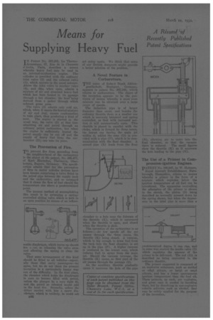
A Novel Feature in Carburetters.
THE mune of Itobe-A Bosch .Aktien gesellsehaft, Stuttgsrt, Germany, appears in patent No. 367,168, which relates to carburetters. The object of the invention appears to he the provision' of means whereby a more even mixture can be obtained over a large range of speeds.
The induction pipe is of larger diameter than usual, and besides the ordinary throttle there is a smaller one which is unevenly balanced and spring controlled, so that with increased suction it will automatically open. This throttle is placed in parallel with the choke, which is formed by three cones, the lowest one havingthe main jet within it, whilst the cone (D) is provided with a pipe (F), which is in communication with the float chamber. A second pipe (N) leads from the float
chamber to a hole near the fulcrum of the throttle (K), which is uncovered when the throttle is open, and closed when the throttle is shut.
The operation of the e.arburetter is RR follows :—At low speeds all the air passes through the +lire° cones, the throttle (K) being closed. A vacuum, which is big enough to draw fuel from the tank into the float chamber, is set up in the pipe (F). A higher vacuum is produced in the lowest cone, which induces fuel to spray from the main jet. Should the vacuum increase, the throttle (K) opens, so that part of the air passes through the passage (I).
As the auxiliary throttle gradually opens it uncovers the hole of the Pipe N), allowing air to enter into the float chamber, so that the vacuum there is reduced. The small figures show the throttle (K) as it uncovers the hole leading to the pipe (N).
The Use of a Primer in Compression-ignition Engines.
PATENT No. 366,947, by W. Helmore,
Royal Aircraft Establishment, Farnborough, Hampshire, relates to means whereby a primer in the form of a mixture which explodes below the ignition temperature of oil fuel can be introduced. The apparatus controlling the admission of the primer is shown in the sketch, the piston (8) being described as normally pressed down by the spring shown, but when the depression in the inlet pipe is more than a
predetermined degree it can rise, and in some way control the needle valve (3) which regulates the amount of the primer to be delivered. The rod (11) is described as being connected to the ordinary throttle.
The primer suggested is composed of an explosive substance, such as methyl or ethyl nitrate, or butyl or amyl nitrate, and has a lower spontaneous ignition temperature than the fuel oil. These primers, as such, are explosive, and great care is needed in handling them, but by dissolving in non-explosive volatile solvents, such as alcohol, they may besafely applied for the purpose of the invention,