 1
1 2
2 3
3 4
4 5
5 6
6 7
7 8
8 9
9 10
10 11
11 12
12 13
13 14
14 15
15 16
16 17
17 18
18 19
19 20
20 21
21 22
22 23
23 24
24 25
25 26
26 27
27 28
28 29
29 30
30 31
31 32
32 33
33 34
34 35
35 36
36 37
37 38
38 39
39 40
40 41
41 42
42 43
43 44
44 45
45 46
46 47
47 48
48 49
49 50
50 51
51 52
52 53
53 54
54 55
55 56
56 57
57 58
58 59
59 60
60 61
61 62
62 63
63 64
64 65
65 66
66 67
67 68
68 69
69 70
70 71
71 72
72 73
73 74
74 75
75 76
76 77
77 78
78 79
79 80
80 81
81 82
82 83
83 84
84 85
85 86
86 87
87 88
88 89
89 90
90 91
91 92
92 93
93 94
94 95
95 96
96 97
97 98
98 99
99 100
100 101
101 102
102 103
103 104
104 105
105 106
106 107
107 108
108 109
109 110
110 111
111 112
112 113
113 114
114 115
115 116
116 117
117 118
118 119
119 120
120 121
121 122
122 123
123 124
124 125
125 126
126 127
127 128
128 129
129 130
130 131
131 132
132 133
133 134
134 135
135 136
136 137
137 138
138 139
139 140
140 141
141 142
142 143
143 144
144 145
145 146
146 147
147 148
148 149
149 150
150 151
151 152
152 153
153 154
154 155
155 156
156 157
157 158
158 159
159 160
160 161
161 162
162 163
163 164
164 165
165 166
166 167
167 168
168 169
169 170
170 171
171 172
172 173
173 174
174 175
175 176
176 177
177 178
178 179
179 180
180 181
181 182
182 183
183 184
184 185
185 186
186 187
187 188
188 e weights for the practical mat
Page 48
Page 49
If you've noticed an error in this article please click here to report it so we can fix it.
The CPC exam question on calculating axle weights often has practical men flummoxed, Here Les Oldridge Makes things clec
THE SYLLABUS of the Royal Society of Arts examination for the Certificate of Professional Competence in Road Transport. contains an. item (B1. 2:3): "State methods of calculating axle weights and weight distribution".
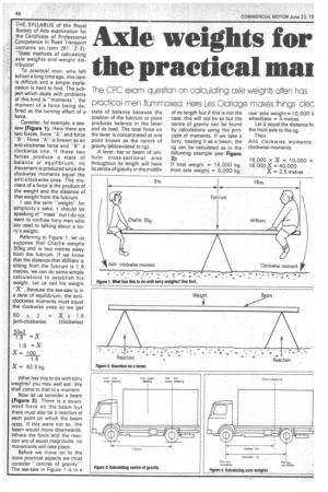
To practical men, who left school a long time ago, this item is difficult and a simple explanation is hard to find. The subject which deals with problems of this kind is "moments", the moment of a force being defined as the turning effect of a. force.
Consider, for example, a seesaw (Figure 1). Here there are two forces, force "A" and force "B". Force "A" is known as an anti-clockwise force and "B" a clockwise one. If these two forces produce a state of balance or equilibrium, no movement is produced since the clockwise moments equal the anti-clockwise ones. The moment of a force is the product of the weight and the distance of that weight from the fulcrum.
I use the term "weight" for simplicity's sake; I should be speaking of "mass" but I do not want to confuse lorry men who are used to talking about a lorry's weight.
Referring to Figure 1, let us suppose that Charlie weighs 50kg and is two metres away from the fulcrum. If we know that the distance that William is sitting from the fulcrum is 1.6 metres, we can do some simple calculations to establish his weight. Let us call his weight "X". Because the see-saw is in a state of equilibrium, the anticlockwise moments must equal the clockwise ones so we get
50 x 2 = x 1.6
(anti-clockwise) ('clockwise) 50x2
1.6 = X 1.6 =X
X= 100 1.6 X= 62.5 kg.
What has this to do with lorry weights? you may well ask. We shall come to that in a moment.
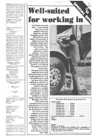
Now let us consider a beam (Figure 2). There is a downward force on the beam but there must also be a reaction at each point on which the beam rests. If this were not so, the beam would move downwards. Where the force and the reaction are of equal magnitude, no movements will take place.
Before we move on to the more practical aspects we must consider "centres of gravity". The see-saw in Figure 1 is in a state of balance because the position of the fulcrum or pivot produces balance in the lever and its load. The total force on the lever is concentrated at one point known as the centre of gravity (abbreviated to cg).
A lever, bar or beam of uniform cross-sectional area throughout its length will have its centre of gravity in the middle of its length but if this is not the case, this will not be so but the centre of gravity can be found by calculations using the principle of moments. If we take a lorry, treating it as a beam, the cg can be calculated as in the following example (see Figure 3): If total weight = 16,000 kg; front axle weight = 6,000 kg; rear axle weight = 10,000 k wheelbase = 4 metres Let X equal the distance frc the front axle to the cg.
Then Anti clockwise moments clockwise moments
16,000 x X = 10,000 x
16,000X = 40,000 X = 2.5 metres his is still not what we are ing for; it is not what the man requires because he Js to know axle weights, but are getting near to our ictive now. Taking another • at our last calculation
ii weight X distance from Yt axle to cg = rear axle ght x wheelbase
I weight X distance from it axle to cg wheelbase ear axle weight
low we can look at the pracaspects. Instead of using term centre of gravity, let us ;ider the centre payload line I uniformly loaded vehicle. lure 4). Using the centre of front wheel as the datum, distance to the payload line _) and the distance between axles can be measured. The ler is the loadbase and the 3r the wheelbase. The foling formula, derived from one above will now form the
s of all load calculations: 'ayload on rear axle = payload X loadbase wheelbase
-he following example shows if the formula works.
inladen axle weights front 2000 kg Rea 'r 3000 kg load = 9000 kg dbase = 2.5 metres eelbase = 4 metres aunt of payload on rear axle = Payload X Loadbase Wheelbase = 9000 X 2.5 4 = 22,500 4 = 5625 kg (punt of payload on front axle ayload — rear axle payload 3000 — 5625 3375 kg
al weight on rear axle )ayload on rear axle JW on rear axle
5625 + 3000 3625 kg al weight on front axle
JW on front axle + Payload Dn front axle
2000 + 3375 5375 kg For examination purposes all t is really necessary is to morise the last formula I have en and then be able to calcu: front and rear axle weights
Ti it.