


A Coupling Joint for Trailers
Page 62
If you've noticed an error in this article please click here to report it so we can fix it.
A R6unie of Recently Published Patent Specifications
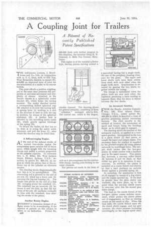
THE well-known concern, J. Brock1 house and Co., Ltd., in conjunction with A. T. C. Dear, both of Hill Top, West Bromwich, disclose in patent No. 410,095 an improved form of joint for the attachment of a trailer to its tractor vehicle.
This joint affords a positive coupling, yet at the same time possesses the properties of universal movement and simplicity of release. Attached to the tractor chassis is a spherically ended bracket (5), which forms the towing member. The trailer drawbar carries a corresponding hollow spherical cup (6) adapted to fit over the towing ball. A sprung lever (1) working in a slot in the drawbar is used to lock the cup in position, by means of the spherical abutment (4). A further lock is afforded by the swivelling safety catch (2), which guards against breakage of the spring (3).
To detach the trailer, all that has to be done is to swing the safety catch sideways, and pull the lever (1), after which the drawbar may be lifted clear.
A Self-scavenging Engine.
AT the end of the exhaust stroke of a normal four-stroke engine the compression space remains full of burnt gases, which mingle with the incoming charge and nullify a certain proportion of the cylinder capacity. To overcome this, L, N. Miller, 221, West Jackson Street, Elkhart, Indiana, U.S.A., describes, in patent No. 408,114, an engine in which the piston rises to the extreme top of the cylinder on alternate strokes.
The drawing shows diagrammatically how this is to he accomplished. The connecting rod is pivoted to the end of an arm (5) which has a lower arm (3) carrying the big-end bearing (4). The longer arm pivots on the end of a link (6), swinging about the camshaft (1). The camshaft has an eccentric (2) between it and the link, so that the fulcrum of the arm (6) oscillates vertically in time with the camshaft, thus altering the stroke of the piston.
Another Rotary Engine.
INTEREST in heterodox designs of enigine seems to be re-awakening, if the number of patents on this subject be taken as an indication. Patent No. B48 409,662 deals with further progress in this direction, the inventor being H. B. Ormerod, 3, Belle Vue Terrace, Bury, Lancs.
This engine is of the toroidal cylinder type, having pistons moving around a circular channel. The drawing, shows the general assembly, consisting of three " cylinders " arranged side-by-side. The central one, which is the largest, acts as a pre-compressor for the combustible charge, having ports leading to the outer channels.
The pistons are made in the form of
a gearwheel having but a single tooth, the rest of the periphery forming clear
ance for the gases. The upper and lower shafts each have three rotors; these mesh with each other when the single teeth meet. Synchronism is attained by gearing the two shafts together outside the casing. The charge is introduced when the piston teeth are near each other, the explosion producing a force tending to separate them; thus the drive is shared between the two shafts.
An Automatic Gearbox. •
FROM the Bendix Aviation Corporation, 105, West Adams Street, Chicago, U.S.A., comes patent No. 409,484 in which is described a form of gearbox possessing several interesting features. The chief novelty is the method of control, the interaction of speed and torque being the deciding factor as to which gear is engaged.
The drawing shows the nucleus of the automatic control, as applied to a twospeed gearbox. Incorporated in the box is a plate clutch (1) that serves to couple the input and output shafts. The necessary force for contact is supplied by the pivoted weights (2) being pressed outwards by centrifugal force. The output shaft carries also the low-gear pinion (4) which meshes with a layshaft gear in the usual manner, This pinion has, however, a one-way roller clutch (5) between it and its shaft, so that whilst top gear is in operation it may over-run. In addition, the pinion is mounted on a coarse thread (not shown) so that a load produces an endwise. thrust against a powerful spring (3).
In operation, the mechanism is first of all engaged by means of a dog clutch and the engine speeded up. If the load he greater than the plate clutch can transmit, slip takes place, up to the point when the one-way clutch ceases to over-run; after this the second gear takes charge.
The load on the coarse thread of the low-gear pinion causes endwise movement, which presses the 'clutch plates out of engagement, so that no heating occurs as the result of slip. When the load falls; the coarse thread eases off; the clutch plates engage, and top• gear operates, the clutch pressure increasing centrifugally as the engine speed rises.