


A MOTOR WINDLASS FOR PLOUGHING.
Page 36
If you've noticed an error in this article please click here to report it so we can fix it.
A Résumé of Recently Published Patents.
We should think that the principal advantages of the motor windlass which is patented in specification No. 142,690 by . and H. McLaren, Ltd., are its
light weight and its simplicity. In practice it is intended that it should take the place of the usual double-engine set of steam tackle for ploughing and
cultivating, etc. Two of the motor windlasses will constitute a set for that purpose.
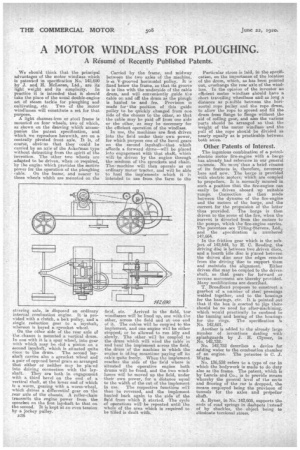
A light channeniron or steel frame is mounted on four wheels, two of which, as shown on the drawing whioh accompanies the patent specification, and which we reproduce herewith, are on a centrally pivoted front. axle. It is, of course, obvicns that they could be carried by an axle Of the Ackerman type without detracting from the spirit of the invention. The other two wheels are adapted to be driven, when k o required, by the engine which provides the motive power for the operation, of the ploughing
cable. On the frame, and nearer to those wheels whith are mounted on the steering: axle, is disposed an ordinary internal combustion engine. It is provided with a clutch, a belt pulley, and a single reduction gear to a layshaft; whereon is keyed a sprocket wheel. On the other side of the rear axle of the. chassis is mounted a vertical drum. In one with it is a spur wheel, into gear with which may be nlid a pinion on a second layshaft, which is situated quite
close to the drum. The second layshaft carries also a sprocket wheel and a pair of opposed bevel gears so arranged that either or neither may be placed into driving connection with the layshaft. They are both in engagement with a third bevel on the end of a vertical shaft, at the lower end of which is a worm, gearing with a worm-wheel, which drives a differential gear on the rear axle of the chassis. A roller-chain transmits the engine power from the sprocket on the first layshaft to that on the second. It is kept at an even tension by a jockey pulley.
n38
Carried by the frame, and midway between the two axles of the machine, issa V-grooved horizontal pulley. It is fixed below the frame, so that its groove is in line with the underside of the cable drum, and will conveniently guide the cable on and off the drum as the plough is hauled to and fro. Provision is made for the position of this guide pulley to be quickly changed from me side of the chassis to the other, so that the cable may be paid off from one side or the other, as may be necessary for the efficient operation of the windlass.
In use, the machines are first driven into the field under their own power, for which purpose one of the bevel gears on the second layshaft—that which affords a forward drive—will be placed into engagement with that shaft, which will be driven by. the engine through the medium of the sprockets and chain. Thozmachine will then operate as an ordinary motor tractor, and will be able to haul the implements which it is intended to use from the farm to the field, etc. Arrived in the field, the' windlasses will be lined up, one with the other, across the field and at one end of it. The cables will be coupled to the implement, and one engine will be either stopped, or be allowed to run idly and slowly. The other will be coupled to the drum which will wind the cable in and haul the implement across the field, , the drum of the machine in which the engine is idiing meantime paying off its cable quite freely. When the implement reaches the side of the field where is situated the operative engine both drums will be freed, and the two windlasses will be moved up the field, under their own power, for a distance equal to the width of the cut of the implement in use. The respective functions wil then be reversed, and the implement hauled back again to the side of the field from which it etarted. The cycle of operations will be repeated until the whole of the area which is required to be tilled is dealt with. Particular stress is laid, in the specification, on the importance of the location of the drum, which, as has been pointed out overhangs the rear axle of the windlass. In the opinion of the inventor an efficient motor windlass should have a short traveling wheelbase and as long a distance as p.ssible between the horizontal rope pulley and the rope drum, to allow the rope to spread and fill the drum from flange to flange without the aid of coiling gear, and also the various parts should be arranged so that the weight of the motor windlass and the pull of the rope should be divided as nearly equally as is practicable between
both axles.
Other Patents of Interest.
The ingenious combination of a petrolelectric motor fire-eligine with a barge has already had reference in our general co.umne No more-than a brief résumé of its features is, therefore, necessary here and now. The barge is provided with electric motors, which are coupled to propellers. It is normally moored in such a position that the fire-engine can easily be diiven aboard up suitable ramps. Connection is then mode between the dynamo of the fire-engine and the motors of the barge' and the current for the propulsion of the latter thus provided. The barge is then driven to the scene of the fire, when the urrent is diverted from the motors to the pumps, which the fire-engine carries. The patentees are Tilling-Stevens, Ltd., and the specification is numbered 142,664.
In the friction gear which is the subject of 142,644, by H. C. Reading, the driving disc is between two driven discs, and a fourth idle disc is placed between the driven disc near the edges remote from the driving disc to support them and maintain the alignment. Either driven disc may be coupled to the driven shaft, so that gears for forward or reverse movement are thereby provided. Many modifications are described.
T. Broadbent proposes to construct a gearbox of a number of steel pressings welded together, and to the housings for the bearings, etc. It is pointed out that if the box is erected to jigs there should be no need for after-machining, which would practically be confined to the turning and boring of the housings for the rings. The specification 78, No. 142,691.
Another is added to the already large number of inventions dealing with eplashtuards by J. H. Clymer, in No. 142,732.
No. 142,752 describes a device for adding water to the combuetion eharaber
of an engine. The patentee is C. tit Watts.
No. 136,538 refers to a type of car in which the bodywork is mane to do duty also as the frame. The patent, which Is by Lancia and Co., is to provide means Whereby the general level of the sects and flooring of the car is dropped, the means employed being the provision of tunnels for the axles and propellor shaft.
A. Ryner, in No. 142.605, supports the ends of road springs in dashpots iastead• of by shackles, the object being to eliminate torsional stress.