


Patents Completed.
Page 18
If you've noticed an error in this article please click here to report it so we can fix it.
Complete specifications of the following patents will be sent to any:address in the United Kingdom upon receipt of eightpence per copy at the Sale Branch, Patent Office, Holborn, W.C.
VALVE RODS.—Burt.—No. 15,900, dated 2nd July, 1910.—In the construction described in this specification there is introduced, between the actuating cam and the stem of the valve to be operated, a tappet or rod moving in a guide and provided with an adjustable head. Several variant constructions are described and illustrated in the specification. In the one herewith illustrated, the tappet is provided with a recessed head screwed into it to provide longitudinal adjustment. In the recess in the head a suitable helical spring is carried, and this bears against a plate formed on the end of the valve rod. The ordinary spring for controlling the valve is quite separate from this helical spring. With this construction the cap is maintained in constant contact with the end of the valve stem, and the lower end of the tappet is likewise maintained in constant contact with the actuating cam. One great, advantage attending the use of such a device is that, as there is no make and break contact between the moving parts, the noise i5 reduced to a minimum.
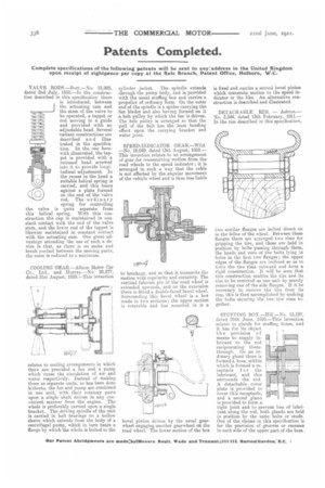
COOLING GEAR.—Albion Motor Car Co., Ltd., and Murray.—No. 20,277, dated 31st August, 1910.—This invention
relates to cooling arrangements in which there are provided a fan and a pump which cause the circulation of air and water respectively. Instead of making these as separate units, as has been done hitherto, the fan and pump are combined in one unit, with their rotatory parts upon a single shaft driven in any convenient manner from the engine. The whole is preferably carried upon a single bracket. The driving spindle of the unit is carried in ball bearings on a hollow sleeve which extends from the body of a centrifugal pump, which in turn bears a flange by which the whole is bolted to the cylinder jacket. The spindle extends through the pump body, and is provided with the usual stuffing box and carries a propeller of ordinary form. On the outer end of the spindle is a spider carrying the fan blades and also having formed on it a belt pulley by which the fan is driven. The belt pulley is arranged so that the pull of the belt has the least bending effect upon the carrying bracket and water joint.
SPEED-INDICATOR GEAR.—Wild. —No. 19,049, dated 13th August, 1910.— This invention relates to an arrangement of gear for transmitting motion from the road wheels to the speed indicator ; it is arranged in such a way that the cable is not affected by the angular movement of the vehicle wheel and is thus less liable to breakage, and so that it transmits the motion with regularity and certainty. The vertical fulcrum pin of the road wheel is extended upwards, and on the extension there is fitted a double-faced bevel wheel. Surrounding this bevel wheel is a box made in two sections ; the upper section is rotatable and has mounted in it a bevel pinion driven by the usual gearwheel engaging another gearwheel on the road wheel. The lower section of the box is fixed and carries a second bevel pinion which transmits motion to the speed indicator or the like. An alternative construction is described and illustrated.
DETACH .ABLE RIM. — Ashton.— No. 3,544, dated 13th February, 1911.— In the rim described in this specification, two similar flanges are bolted direct on to the felloe of the wheel. Between these flanges there are arranged two rims for gripping the tire, and these are held in position by bolts passing through them, the heads and nuts of the bolts lying in holes in the first two flanges; the upper edges of the flanges are inclined so as to force the tire rims outward and form a rigid construction. It will be seen that this construction enables the tire and its rim to be removed as one unit by merely removing one of the side flanges. If it be necessary to remove the tire from its rim, this is then accomplished by undoing the bolts securing the two tire rims together.
STUFFING BOX—Hill—No. 15,197, dated 25th June, 1910.—This invention relates tn glands for stuffing boxes, and it has for its object, the provision of means to supply lubricant to the rod reciprocating therethrough. On an ordinary gland there is formed a boss, within which is formed a receptacle for the lubricant, and this surrounds the rod. A detachable cover plate is provided to cover this receptacle, and a second gland is provided to form a tight joint and to prevent loss of lubricant along the rod, both glands are held in position by the same bolts or studs. One of the claims in this specification is for the provision of grooves or recesses in each side of the upper part of the boss.