


I n 1983 Mercedes-Benz brought in 159kW (213hp) engined 6x4s with
Page 83
Page 84
Page 85
Page 86
If you've noticed an error in this article please click here to report it so we can fix it.
a choice of 3.6, 4.2 and 4.8m wheelbases. In those days it played the
power game along with the rest but by the time CM tested the 2421 in early 1989 it was looking a little on the weak and feeble side. However, it was taking fourth place in its market behind Leyland Daf, Iveco Ford and Volvo.
Now with the peak in the tipper market long past many of the vehicles
bought during the boom are with their second or third owners. Many of these oprators want to carry out their own servicing so this month we are covering the 2421.
There are three levels of service; lube, maintenance and maintenance+ ancilliary. The 24-21 is in maintenance category 11 and requires a lubrication service every 10,000km and a mainte nance service every 20,000km. There are additions to every second, third and sixth maintenance service (main tanance +). Standard times for the lube service is 2.2 hours; maintenance, 6.2 hrs; maintenence plus additional (2nd) 7.6 hrs, 7.2 hrs (3rd), and 8.3 (6th).
Our vehicle, an F-registered example with 174,000km on the clock, recieved a maintenance service in the workshops of M-B dealer Rygor Commercials, Westbury, Wiltshire.
The service was carried out by Tony Marsh who has been working on Mercedes trucks for more than 4% years.
Parts prices (retail ex-VAT) are: oil filter £10.96; fuel filter £9.30; pre-filter £1.56; rocker cover gasket (x6) £1.99 each.
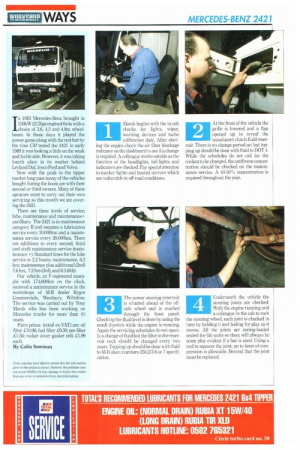
By Colin Sowrnan Marsh begins with the in-cab checks for lights, wiper, warning devices and tacho calibration date. After starting the engine check the air filter blockage indicator on the dashboard to see if a change is required. A colleague works outside as the function of the headlights, tail-lights and indicators are checked. Pay special attention to marker lights and heated mirrors which are vulnerable in off-road conditions.
1
The power steering reservoir is situated ahead of the offside wheel and is reached through the front panel. Checking the fluid level is done by using the small dipstick while the engine is running. Again the servicing schedules do not specify a change of fluid but the filter in the reservoir neck should be changed every two years. Topping up should be done with fluid to M-B sheet numbers 236.2/3/6 or 7 specification.
3
At the front of the vehicle the grille is lowered and a flap opened up to reveal the translucent clutch fluid reservoir. There is no change period set but topping up should be done with fluid to DOT 4. While the schedules do not call for the coolant to be changed, the antifreeze concentration should be checked on the maintenance service. A 40-50% concentration is required throughout the year.
Underneath the vehicle the steering joints are checked. With the engine running and a colleague in the cab to rock the steering wheel, each joint is checked in turn by holding it and feeling for play as it moves. All the joints are spring-loaded sealed-for-life units so there will always be some play evident if a bar is used. Using a tool to squeeze the joint, up to 4nun of compression is allowable. Beyond that the joint must be replaced.
4
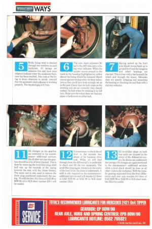
Brake lining wear is checked through two windows in each backplate. All linings are asbestos free and have wear ridges to indicate when the minimum thickness has been reached. Also look at the lining to drum clearance to satisfy yourself that the automatic slack adjuster is working properly. The required gap is 0.7mm. The auto slack adjusters fitted to the 2421 also carry a lining wear indicator. When the pointer moves around to the mark in the housing (highlighted in yellow above) the lining should be replaced. Marsh warns against relying solely on these indicators as they could have been wrongly set up in the past. Check that the lock stops on the steering axle are set correctly: they should contact the hub when the steering is on full lock. Make sure the wheel does not foul any pipes or bodywork on either lock.
Having jacked up the front axle Marsh moves back up to ground level and the kingpins and wheel bearings are checked. This is done with a bar beneath the wheel and through the knave. Mercedes does not specify stripping and repacking the bearing or checking the end float with a dial test indicator.
7
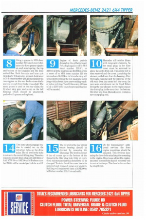
Using a grease to M-B sheet number 267 Marsh now lubricates the three grease nipples on each road spring, the top and bottom of the kingpins and the front anti-roll bar. Both the main and inter axle propshafts' UJs are also greased. Lubricant to M-B sheet number 266.2 is needed for the two nipples on the rear brake cross-shafts and one on each front brake crass-shaft. The same grease is used on the rear slider, the flywheel ring gear and a cup on the bell housing which should be unscrewed, packed with grease and replaced. Engine oil drain periods depend on the oil being used. For a high quality oil to M-B sheet number 227.0/1, or 228.011/2/3) the intervals are 20,000km while a lesser oil to M-B sheet number 226 the intervals are 10,000km. A 14mm hexkey will be needed to remove the non-magnetic sump plug which should have a new sealing washer before refitting. To refill the sump 18 litres of oil to 15W/40 to your chosen specification will be needed,
10 Mercedes still retains filters
with renewable elements. So the small plug in the filter cover must be removed to allow the oil to drain out. The centre bolt is then removed and the cover, containing the element, withdrawn from the housing. After thorough cleaning and the removal of the old seals from the centre bolt the cover, the new seals and element can be fitted. When fitting the new element to the engine ensure the drain plug in the cover is at the bottom. Oil filter kits from Mercedes also contain a new sump plug seal.
11 Oil changes on the gearbox
are restricted to the mainte nance+ additional services.
On all other services the gearbox should have its oil level checked. This is done by removing the level/filler plug, sited half way up the nearside of the casing towards the rear, with the 14mm hexkey. The same tool is also used to remove the drain plug positioned underneath the casing. To refill the box 18.5 litres of SAE 80 or 80W/85 oil to M-B sheet number 235.1 will be needed.
12 It is necessary to check the oil
level in the transfer box ahead of the foremost drive axle. While oil will feed through from the differential it is preferable to check and fill the two separately. The level/filler plug (again 14mm) is in the centre of the front cover, the drain is underneath. A refill is only required on the maintenance+ additional service and will require 2.5 litres of SAE 85W/90 or SAE 90 to M-B sheet number 235.0.
13 Oil level/filler plugs on both
rear axles are situated in the centre of the differential cov ers, the drains are underneath the casings. Oil changes are again restricted to the maintenance+ additional services while a level check should be done on all other visits to the workshop. With the transfer gearing separated from the front differential each rear axle requires 8.0 litres of SAE 85W/90 or SAE 90 to M-B sheet number 235.0 for a refill.
14 The same check/change rou
tine is carried out on the reduction hubs on the drive axles. The oil level in the hubs is not up to the central filling plug. There is a separate smaller drain plug and 3.25 litres of SAE 85W/90 or SAE 90 to M-B sheet number 235.0. will be needed per hub for a refill.
15 The oil level in the rear spring
centre bearing should be checked by removing the filler plug, The level is correct if the oil comes up to the bottom of the thread in the filler plug hole. Only on every third maintenance service should the oil be changed. To drain the oil the cover has to be removed and replaced using new gaskets. Refilling will require 0.6 litres of SAE 90 to M-B sheet number 235.0 for each side.
16 On the maintenance+ additional services the front
engine mountings should be adjusted. This involves loosening the three bolts attaching the mounting to the engine. Once loose adjust the enginemounted eye until the chassis mounted web is central in the eye. The three bolts can then be retightened.
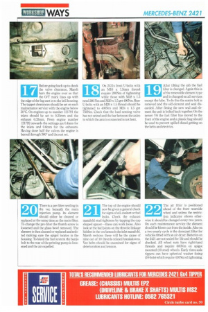
17 Before going back up to check
the valve clearance, Marsh bars the engine over so that the 0/T mark lines up with the edge of the lug cast in to the bell housing The tappet clearances should be set on each maintenance service with the engine below 30°C. On engines up to number 121791 the inlets should be set to 025mm and the exhaust 0.35mm. From engine number 121792 onwards the settings are 0.4mm for the inlets and 0.6mm for the exhausts. Having done half the valves the engine is barred through 360° and the rest set.
18 On 2421s front U-bolts with
an M16 x 1.5mm thread require 200Nm of tightening while those with M18 x 1.5 need 280 Nrn and M20 x 1.5 get 400Nm. Rear U-bolts with an M20 x 1.5 thread should be tightened to 400Nm and M24 x 1.5 get 750Nm. Check that the load sensing valve has not seized and the bar between the axles to which the arm is connected is not bent.
19 After tilting the cab the fuel
filter is changed. Again this is of the renewable element type and is changed on all services except the lube. To do this the centre bolt is removed and the old element and seal discarded. After fitting the new seal and element the unit is bolted back together. On the newer V6 the fuel filter has moved to the front of the engine and a plastic bag should be used to prevent spilled diesel getting on the belts and electrics.
20 There is a pre-filter nestling in
the vee beneath the main injection pump. Its element should either be cleaned or replaced at the same time as the main filter. To change the pre-filter the thumb screw is loosened and the glass bowl removed. The element is then cleaned or replaced and refitted making sure the spigot locates in the housing. To bleed the fuel system the banjo bolt to the rear of the priming pump is loosened and the air expelled.
21 The top of the engine should
now be given a general check for signs of oil, coolant or fuel leaks. Check the exhaust manifold stud tightness by tapping the cup shaped spacer—these can work loose. Also look at the ball joints on the throttle linkage hidden in the vee beneath the inlet manifold. Marsh reckons these will be the cause of nine out of 10 throttle-related breakdowns. Vee belts should he examined for signs of deterioration and tension.
22 The air filter is positioned
ahead of the front nearside wheel and unless the restric tion indicator shows otherwise it should be changed every two years. On each maintenance service the element should be blown out from the inside. Also on a two-yearly cycle is the desiccant filler for vehicles fitted with an air dryer. Batteries on the 2421 are not sealed for life and should be checked. All wheel nuts have right-hand threads and require 600Nm on spigot mounted (10-stud) wheels. Early three-axle tippers can have spherical washer fixing (10-hole) which require 450Nm of tightening.