


A Self-governing Injection Pump
Page 64
If you've noticed an error in this article please click here to report it so we can fix it.
1-1 A N injection pump of the rotary
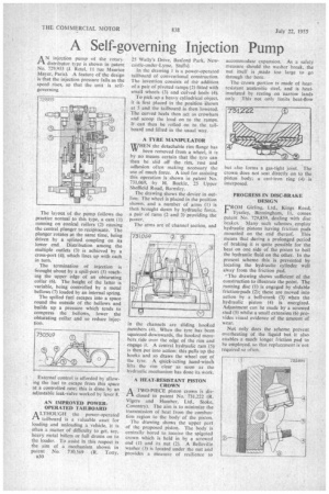
distributor type is shown in patent No. 729,935 (J. Retel, 11 rue Maurice Mayer, Paris). A feature of the design is that the injection pressure falls as the speed rises, so that the unit is selfgoverning.
The layout of the pump follows the practice normal to this type, a cam (I) running on conical rollers (2) causing the central plunger to reciprocate. The plunger rotates at the same time, being driven by a splined coupling on its lower end. Distribution among the multiple outlets (3) is achieved by a cross-port (4), which lines up with each in turn.
The termination of injection is brought about by a spill-port (5) reaching the upper edge of an obturating collar (6). The height of the latter is variable, being controlled by a metal bellows (7) loaded by an internal spring.
The spilled fuel escapes into a space round the outside of the bellows and builds up a pressure which tends to compress the bellows, lower the obturating collar and so reduce injection.
External control is afforded by allow ing the fuel to escape from this space at a controlled rate; this is done by an adjustable leak-valve worked by lever 8.
AN IMPROVED POWEROPERATED TAILBOARD
A LTHOUGH the power-operated rTht tailboard is a valuable asset for loading and unloading a vehicle, it is often a matter of difficulty to get, say, heavy metal billets or full drums on to the loader. To assist in this respect is the aim of a mechanism shown in patent No. 730,569 (R. Totty,
1530 23 Wally's Drive, Basford Park, Newcastle-under-Lyme, Staffs).
In the drawing I is a power-operated tailboard of conventional construction. The invention consists of the addition of a pair of pivoted ramps (2) fitted with small wheels (3) and cuived heels (4).
To pick up a heavy cylindrical object, it is first placed in the position Shown at 5 and the tailboard is then lowered. The curved heels then act as crowbars and scoop the load on to the ramps. It can then be rolled on to the tailboard and lifted in the usual way.
A TYRE MANIPULATOR
WHEN the detachable rim flange has been removed from a wheel, it is by no means certain that the tyre can then be slid off the rim, rust and adhesion often making necessary the use of much force. A tool for assisting this operation is shown in patent No. 731,069, by H. Buckle, 25 Upper Sheffield Road, Barnsley.
. The drawing shows the device in outline. The wheel is placed in the position shown, and a number of arms (1) is then brought down by hydraulic force, a pair of rams (2 and 3) providing the power.
The arms are of channel section, and in the channels are sliding hooked members (4). When the tyre has been squeezed downwards, the hooked members ride over the edge of the rim and engage it. A central hydraulic ram (5) is then put into action; this pulls up the hooks and so draws the wheel out of the tyre. A qUick-acting hand-winch lifts the rim clear as soon as the hydraulic mechanism has done its work.
A HEAT-RESISTANT PISTON CROWN
.1-1 A TWO-PIECE piston crown is dis closed in patent No. 731,222 (R. Vigcrs and Humber, Ltd., Stoke, Coventry). The aim is to minimize the transmission of heat from the combustion region to the body of the piston.
The drawing shows the upper part of the proposed piston. The body is centrally bored to receive the spigoted crown which is held in by a screwed end (I) and its nut (2). A Belleville washer (3) is located under the nut and provides a measure of resilience to accommodate expansion. As a safety measure should the washer break, the nut itself is made too large to go through the bore.
The crown portion is made of heatresistant austenitic steel, and is heatinsulated by resting on narrow lands only This not only limits heat-flow but also forms a gas-tight joint. The crown does not seat.directly on to the piston body; a cast-iron ring (4) is interposed.
PROGRESS IN DISC-BRAKE DESIGN
CROM Girling, Ltd., Kings Road,
Tyseley, Birmingham, II, comes patent No. 729,859, dealing with disc brakes. Many such schemes employ hydraulic pistons having friction pads mounted on the end thereof. This means that during a prolonged period of braking it is quite possible for the heat on one side of the piston to boil the hydraulic fluid on the other. In the present scheme this is prevented by locating the hydraulic cylinder well away from the friction pad.
The drawing shows sufficient of the construction to illustrate the paint. The running disc (1) is engaged by slidable friction-pads (2); these are moved into action by a bell-crank (3) when the hydraulic piston (4) is energized. Adjustment can be made by a screwed stud (5) whilst a small extension (6) provides visual evidence of the amount of wear.
Not only does the scheme prevent overheating of the liquid but it also enables a .much longer friction pad to he employed, so that replacement is not required so often.