


A NEW SPRAG SAFEGUARD.
Page 9
Page 10
If you've noticed an error in this article please click here to report it so we can fix it.
A New Adaptation of the Ratchet and Pawl Principle, with the Addition of an Automatically Acting Disc to Keep the Pawls out of Engagement Until Needed.
WE HAVE, for some time, urged the necessity for some reliable device by means of which accidents due to vehicles running backwards when on hills should be made impossible ; hence we are pleased to see that at least one concern has 1 ecognized the need for catering for the demand that
must arise so soon as it becomes known that reliable fittings are available.
The plan we have suggested is one where the spragging ,Jfect can only be thrown out of action by putting the gear into reverse.
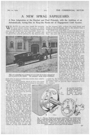
Such a device has now been placed on the market by the Cirac Automatic Reverse Control Co., of San Francisco, and is known as the Shaflock. It is marketed in this country by the Rex Transmission eo., of 3, Portsmouth Street, London, W.C.2. One of our illustrations shows a vehicle standing on a hill of one in four, just as the driver has left it after putting the gear into neutral and without applying the brake. The gradient of the hill shown in the illustration is one in four oetrially 24.8 per cent), a fact which is peculiarly impressive as demonstrating the effectiveness of the device. Apart from the safety afforded by the use of such a sprag, there is the convenience of being able to give the vehicle an easy and smcth start
up the steepest hills, without the usual shock and strain to the Mechanism due to the restart from a stamding position with brake on.
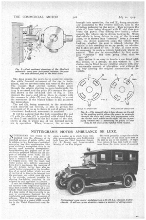
As will be seen from Figs. 1 and 2, the gear can be fitted in a neat box situated behind the gearbox. In Fig. I the plate (E) is shown removed and reversed, so as to show the ratchet teeth, which are in the form of recesses formed in the face of the plate. This plate is attached to the universal joint, and is secured to the driving shaft in the usual nth-rater.
The plate (13) is secured to • the gearbox in such a manner that it cannot revolve. This plate carries the pawls, which are four in number, and are actuated by small springs, which cause them to engage the recesses in the plate (E) should the car run backward.
So far the arrangement is similar to many we have seen before. The plate (C) however, is the essential feature of the invention, as it is pressed against the revolving plate (E) by means of a light spring, shown at Or in Fig. 2. The slight friction thus set up causes the disc (C) to be dragged in the direction in which the plate (E) is revolving ; that is, in the direction indicated by the arrow in Fig. 1, The plate (C) has four slots cut in it, through which the pawls can protrude and engage in the recesses; but, if the plate be partly rotated by the friction between it and plate E, the yortions of plate C between the slots serve to depress the pawls, and so prevent their engagement with the recesses. The drag causes the pawls to be rendered inoperative while forward movement of the car is maintained, and so prevents noise and wear of the pawls. The instant that altered motion takes place through the vehicle starting to move backwards, the drag is reversed and the plate (C) assumes the position shown in the left-hand view of Fig. 3. This exposes the pawls and allows them toengage with the recesses in plate (E) and, by so doing, to arrest the movement of the vehicle before it has gathered any momentum.
The rod (E), being connected to the mechanism .whieh controls the reverse, is able to govern the movement of 0, so as to throw it out of action when intentional backward movement is required.
It will be noticed that the fork connecting the rod (F) with the plate (C) is provided with slotted holes, so that 0 can oscillate to the full extent of the slot, shown in Fig. 3, whilst any of the forward speeds are in operation. When, however, the reverse is brought into operation, the rod (F), being mechanically connected to the reverse selector, acts in the direction indicated by the arrow. This prevents the plate (C) from being dragged with E, and thus prevents the pawls from coining into action ; consequently the vehicle can be driven backwards. When thevehiele is being driven in any of the forward gears, or is thrown into " neutral " from a forward gear, the device positively stops the vehicle from backing, whether the gear is missed; whether the vehicle is left standing on an up grade, or whether • the hi ales are good or not. It may, in some cases, he necessary to push a vehicle backward whilst in neutral. This can be accomplished by first going into " reverse " and then going from that to " neutral."
This makes it as easy to handle a car fitted with this device, in a garage, as one without it. The device can be fitted to any existing vehicle with only a reasonable amount of alteration, and without in any way altering the original construction of the vehicle.