


MAKING BEST USE OF THE FORD.
Page 22
If you've noticed an error in this article please click here to report it so we can fix it.
Valuable Advice on Every Phase of Ford Transport, Which Will Appeal to the Owner, Driver and Repairer.
IN THIS series of hints concerning the Ford light chassis and ton truck wherever they are employed for commercial purposes, we endeavour to deal with the subject from every view-point, so that the advice given will appeal to the owner, driver, maintenance engineer or mechanic.
We shall welcome for inclusion among the hints those which have proved of value to individual users, and will make suitable remuneration for any such information which we publish.
Readers are recommended to obtain the original " Book of the Ford," which constitutes a complete manual dealing with the Ford car, the van and the truck, 2s. 9d. post free from the offices of this journal.
221.—A Dimming Device for the Off-side Headlight.
When passing horsed vehicles at night, particularly on narrow roads, it is convenient to be able to dim the off-side headlamp without actually switching both off, as otherwise has to be done if dazzle is to be avoided. This dimming can be attained by employ
NI Headij8.hts._._ N92
mg a suitable dimming resistance in the wiring circuit.
The resistance required must be a matter of experiment, for our contributor sent us no further particulars beyond the wiring diagram.
222.—Some Notes on Front Springs.
Owners of Ford trucks are sometimes put to eon.siderable expense and trouble through the snapping of leaves in the front spring. Occasionally the spring breaks right through, but generally only one or two leaves give trouble_ 'These breakages can often be averted by careful inspection of the tic-bolt which passes through the centre of the spring.
After traversing rough pieces of road where the spring has been down to the perches, it is often found that the tie-bolt nut has been pulled off, leaving two or three of the leaves entirely dependent on the clamps This in itself lessens the resisting power of the spring, and a new bolt should be fitted immediately.
In order to dismantle the front spring, lift the weight off it by jacking Bp the chassis members at each side. It may be found necessary to disengage the radius rods, which meet in a ball joint under the crankcase, and care must be taken not to snap off the rods at the ends.
There are seven leaves in the front spring, and some time ago the makers introduced a new intermediate leaf, making eight in all. This new leaf should be placed next to the main bottom leaf, and B40 if employed will overcome most of the trouble and stop the bouncing tendency which is often noticed. Before reassembling the spring, the leaf should be thoroughly well greased, usieg powdered graphite as well.
It may be found a little difficult to get the leaves close enough together for the fitting of the nut on to the tie-bolt, but this task can easily be performed by putting the spring into a vice and pressing the leaves together, or, failing this, a doorway will answer the same Purpose. Our sketch shows an alternative method in which the end leaves are tied down to a board and a jack used between the board and the bottom leaf. The two clamps must be well tightened, as they serve to support the whole spring.
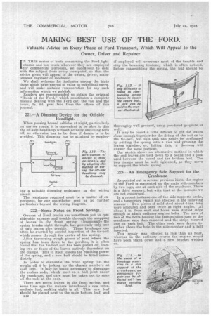
223.—An Emergency Side Support for the .
Crankcase.
As pointed out in several previous hints, the engine of the Ford is supported on the main side-members by two lugs, one at each side of the crankcase. There is a third support, but with that at the moment we are not concerned.
In a recent instance one of the side supports broke, and a temporary repair was effected in the following manner :—Two pieces of mild steel about 6 ins, long were procured and bent twice at right angles. At about 1 in. from each end holes were drilled large enough to admit ordinary engine bolts. The nuts of two of the bolts holding the transmission case to the crankcase were then removed and the strips secured one on each bolt. The other ends were drawn together above the hole in the side-member and a bolt inserted.
This repair was effected in less than an hour, whereas in the ordinary coarse the engine would have been taken down and a new bracket welded on.