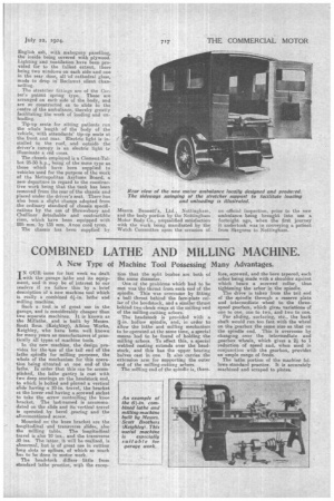
COMBINED LATHE AND MILLING MACHINE.
Page 11

If you've noticed an error in this article please click here to report it so we can fix it.
A New Type of Machine Tool Possessing Many Advantages.
IN OUR issue for last week we dealt .with the garage lathe and its equipment, and it may be of interest to our leaders if we follow this by a brief description of a new machine tool which is really a combined .61-in. lathe and milling machine.
Such a tool is of great use in the garage, and is considerably cheaper than two separate machines. It is known as the Millathe, and is built by Messrs. Scott Bros. (Keighley), Albion Works, Keighley, who have been well known for many years as manufacturers of practically all types of machine tools.
In the new machine, the design provides for the 'use of the tail end of the lathe spindle for milling purposes, the whole of the mechanism for this operation being situated at one end of the lathe. In order that this can be accomplished, the lathe gantry is cast with two deep seatings on the headstock end, to which is bolted and pinned a vertical slide having a 10-in. travel, the bracket at the lower end having a screwed socket to take the screw controlling the knee bracket. The last-named is accommodated on the slide and its vertical travel is operated by bevel gearing and the aforementioned screw.
Mounted on the knee bracket are the longitudinal and transverse slidee, also the milling table. The longitudinal travel is also 10 ins., and the transverse ,30 ins. The latter, it will be realized, is abnormal, but is of great use in cutting Tong slots or splines, of which BO much has to he done in motor work.
The headstock differs little from standard lathe practice, with the excep
tion that the split bushes are both of the same diameter.
One of the problems which had to be met was the thrust from each end of the spindle. This was overcome by fitting a ball thrust behind the face-plate collar of the headstock, and a similar thrust behind two check rings at the milling 'end of the milling-cutting arbors. The headstock is provided with a hollow spindle, and, in order to allow the lathe and milling mechanism to be operated at the same time, a special means bad to be found of holding the milling arbors. To effect this, a special webbed casting extends over the headstock, and this has the upper bearing halves cast in one. It also carries the extension arm for supporting the outer end of the milling-cutting arbors.
The milling end of the spindle is, there_
fore, screwed, and the bore tapered, each arbor being made with a shoulder against which bears a screwed collar, thus tightening the arbor in the spindle.
The drive is taken from the tail end of the spindle through a reserve plate and intermediate wheel to the threespeed gearbox, which gives variations of one to ones one to two, and two to one.
For sliding, surfacing, etc., the back shaft would run too fast with the wheel on the gearbox the same size as that on the spindle end. This is overcome by changing over the intermediate and gearbox wheels, which gives a. 2-1 to 1 reduction of speed and, when used in conjunction with the gearbox, provides an ample range of feeds.
The lathe portion of the machine follows standard practice. It is accurately machined and scraped to plates.


