


Progress in Disc-brake Design
Page 62
If you've noticed an error in this article please click here to report it so we can fix it.
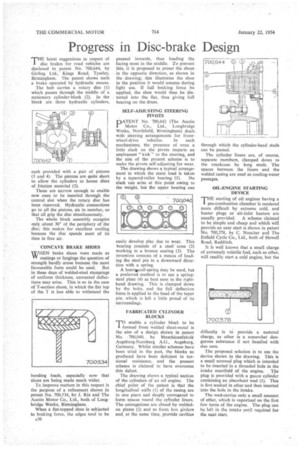
THE latest suggestions in respect of I disc brakes for road vehicles are disclosed in patent No. 700,644, by Girling Ltd., Kings Road, Tyseley, Birmingham. The patent shows such a brake operated by hydraulic means. The hub carries a rotary disc (1) which passes through the middle of a stationary cylinder-block . (2). In the block are three hydraulic cylinders, each provided with a pair of pistons (3 and 4). The pistons are quite short to allow the cylinders to house discs of friction material (5).
These are narrow enough to enable new ones to be inserted through the central. slot when the rotary disc has been removed. Hydraulic connections go to all the pistons, six in number, so that all grip the disc simultaneously.
The whole block assembly occupies only about 300 of the periphery of the disc; this makes for excellent cooling because the disc spends most of its time in free air.
CONCAVE BRAKE SHOES
WHEN brake shoes were made as Ylf castings or ffirgings the question of strength hardly arose because the most favourable form could be used. But in these days of welded-steel stampings of uniform thickness, unwanted deflections may arise. This is so in the case of T-section shoes, in which the fiat top of the T is less able to withstand the
bending loads, especially now that shoes are being made much wider. '
To improve matters in this respect is the purpose of a refinement shown in patent No. 700,534, by J. Rix and The Austin Motor Co„ Ltd., both of Longbridge Works, Birmingham.
When a flat-topped shoe is subjected to braking force, the edges tend to be A36
pressed inwards, thus loading the facing most in the middle. To prevent this, it is proposed to preset the shoes in the opposite direction, as shown in the drawing; this illustrates the shoe in the position it would assume during light use. If full braking force be applied, the shoe would then be distorted into the flat, thus giving full bearing on the drum.
SELF-ADJUSTING STEERING PIVOTS
PATENT No. 700,642 (The Austin Motor Co., Ltd., Longbridge Works, Northfield, Birmingham) deals with steering arrangements for front
wheel-drive vehicles. In such mechanisms, the presence of even a little slack on the pivots imparts an unpleasant " kick " to the steering, and the aim of the present scheme is to make the pivots self-adjusting for wear.
The drawing shows a typical arrangement in which the main load is taken by a tapered-roller bearing (1). No slack can arise at this point owing to the weight, but the upper bearing can
easily develop play due to wear. This bearing consists of a steel • cone (2) working in a bronze seating (3). The invention consists of a means of loading the steel pin in a downward direction with a spring.
A heavAtcoil-spring May be used, but a preferred method is to use a springsteel plate (4) as best seen in the righthand drawing. This is clamped down by the bolts, and the full deflection force is applied to the head of the taper' pin, which is left a little proud of its surroundings.
FABRICATED CYLINDER BLOCKS
TO enable a cylinder block to be I. formed from welded sheet-metal is the aim of a design, shown in patent No. .700,040, by Ma.schinenfabrik Augsburg-Nurnberg A.G., Augsburg, Germany. Whilst similar schemes have been tried in the past, the blocks so produced have been deficient in torsional resistance, and the present scheme is claimed to have overcome this defect.
The drawing shows a typical section of the cylinders of an oil engine. The chief point of the patent is that the longitudinal walls (I) of the casing are in one piece and deeply corrugated to form spaces round the cylinder liners. The corrugations are closed by weldedon plates (2) and so form box girders and, at the same time, provide cavities through which the cylinder-head studs can be passed.
The cylinder liners are, of course, separate members, clamped down to the crankcase by long studs. The spaces between the liners and the welded casing are used as cooling-water passages.
OIL-ENGINE STARTING DEVICE
Tinifstarting of oil engines having a e-combustion chamber is rendered more difficult by extreme cold, and heater plugs or air-inlet heaters are usually provided.' A scheme claimed to be simple and cheap and which will provide an easy start is shown in patent No. 700,378, by C. Nossiter and The Enfield Cycle Co., Ltd., both of Hewell Road, Redditch.
It is well known that a small charge of extremely volatile fuel, such as ether, will readily start a cold engine, but the
difficulty is to provide a metered charge, as ether is a somewhat dangerous substance if nothandled with due care.
The proposed solution is to use the device shown in the drawing. This is a small screwed plug which is intended to be inserted in a threaded hole in the intake manifold of the engine. The plug is provided with a gauze cylinder containing an absorbent wad (1). This is first soaked in ether and then inserted into the hole in the intake.
The wadkcarries only a small amount of ether, which is vaporized on the first few turns of the engine. The plug can be left in .the intake until required for Inc next start.